

In a Time-of-Flight (ToF) sensing system, the VCSEL is the optical transmitter. It emits short infrared pulses or high-frequency modulated light toward a target. The returning photons are collected by a receiver such as a SPAD array or CMOS ToF sensor, and the system calculates distance from either the light’s round-trip travel time or the phase shift of the returned modulation.
The most important distinction is:
- VCSEL = optical transmitter
- SPAD / ToF image sensor = optical receiver
- Timing / phase electronics + processing = distance calculation
A VCSEL does not measure distance by itself. Its role is to generate the optical signal that makes the ToF measurement possible.
VCSELs are attractive for ToF because they can support fast switching, short optical pulses, high-frequency modulation, compact SMD integration, dense emitter arrays and high peak power in array form. This combination has made VCSELs a major source technology for proximity sensing, robot obstacle detection, 3D cameras, face sensing and short-range LiDAR-style systems.
For the VCSEL structure itself, see What Is a VCSEL? Working Principle, Types & Applications.
What Is Time-of-Flight Distance Sensing?
Time-of-Flight measures distance by observing what happens to light after it leaves the sensor, travels to a target and returns.
The simplest conceptual path is:
Emitter → Target → Reflection → Receiver
For direct time-of-flight, the basic relationship is:
Distance = c × Δt / 2
where:
- c = speed of light
- Δt = measured round-trip travel time
The result is divided by two because the light travels the distance twice:
Sensor → Target → Sensor
For example, the transmitter sends a short optical pulse. A fraction of the emitted photons reaches the object, and a much smaller fraction is reflected toward the sensor. The receiver records when those photons arrive and the processing electronics estimate distance.
The basic equation is simple, but practical ToF systems also have to manage ambient light, target reflectivity, detector noise, multipath reflections, optical crosstalk, field of view, temperature and laser-safety requirements.
Direct ToF vs Indirect ToF
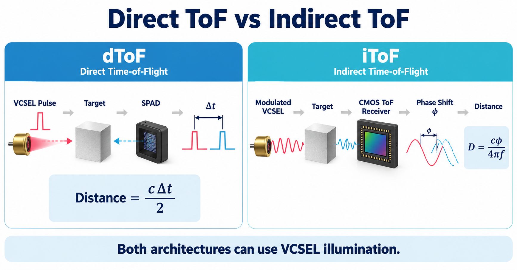
There are two major ToF architectures commonly used in 3D sensing:
- Direct ToF (dToF)
- Indirect ToF (iToF)
Both can use VCSEL illumination, but they measure distance differently.
| Factor | Direct ToF — dToF | Indirect ToF — iToF |
|---|---|---|
| Optical signal | Short pulses | Periodically modulated light |
| Main measurement | Photon arrival time | Phase shift |
| Typical receiver | SPAD + timing electronics | CMOS ToF pixel array |
| Timing element | TDC / histogram | Phase correlation |
| VCSEL requirement | Fast pulsing, high peak power | High-frequency modulation |
| Typical output | Range / multi-zone depth | Dense depth image |
| Typical applications | Proximity, robotics, ranging, LiDAR-like sensing | 3D cameras, machine vision, gesture, in-cabin sensing |
How Direct ToF Works
Direct ToF measures the delay between transmitted optical pulses and returned photon events.
A simplified sequence is:
VCSEL emits pulse → target reflects light → SPAD detects returning photons → TDC measures timing → histogram processing identifies return peak → distance is calculated
ams OSRAM’s current direct ToF devices illustrate this architecture clearly: a 940 nm VCSEL provides the optical transmitter, SPAD pixels detect the reflected photons, time-to-digital converters measure timing, and on-chip processing converts the result into distance.
How Indirect ToF Works
Indirect ToF normally uses continuously or periodically modulated illumination.
A simplified sequence is:
Modulated VCSEL → target → reflected modulation → CMOS ToF receiver → phase-shift measurement → distance
Analog Devices describes continuous-wave ToF cameras as systems that compare the phase of the returning modulated light with the transmitter modulation.
Higher modulation frequency can reduce depth error from a given phase error, but it also reduces the unambiguous distance before phase wrapping occurs. So iToF design balances modulation frequency, depth precision, unambiguous range, receiver bandwidth and VCSEL modulation capability.
For more background, see Analog Devices’ Time of Flight System Design overview.
What Does the VCSEL Actually Do in a ToF Sensor?
A useful way to understand ToF is to divide the system into four parts:
Tx → Scene → Rx → Processing
Tx — VCSEL Transmitter
The VCSEL generates the near-infrared optical signal and strongly influences:
- Wavelength
- Optical power
- Peak power
- Pulse width
- Rise / fall time
- Modulation bandwidth
- Beam divergence
- Array geometry
- Power conversion efficiency
Scene
The scene determines how much optical energy comes back. Important factors include distance, target reflectivity, target angle, surface roughness, multiple objects and ambient sunlight.
Rx — Receiver
The receiver collects returned light. Depending on the architecture, it may include a SPAD array, CMOS ToF pixels, receiver lens and narrow-band optical filter.
Processing
Electronics and algorithms calculate arrival time, phase, histogram peak, confidence, depth, multi-zone distance and 3D depth maps.
The VCSEL supplies the photons. The ToF receiver and processing chain convert returned photons into distance.
How a VCSEL + SPAD dToF Sensor Measures Distance
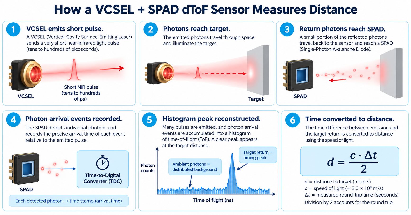
Step 1 — VCSEL Emits a Short Pulse
The driver creates a fast current pulse and the VCSEL converts it into a short optical pulse.
Step 2 — Photons Reach the Target
The beam spreads according to VCSEL divergence and any lens, diffuser, DOE or illumination optics.
Step 3 — The Target Reflects Light
Only a fraction of the optical energy returns toward the receiver. White diffuse surfaces can return much more light than black plastic, dark fabric, grass or other low-reflectivity targets.
Step 4 — SPAD Detects Photon Events
SPAD stands for Single-Photon Avalanche Diode. A SPAD can generate a measurable avalanche event when a photon is detected, making it useful for weak optical returns and precise photon timing.
Step 5 — Timing Events Accumulate into a Histogram
The system repeats the measurement many times. Ambient photons tend to create distributed background events, while target-return photons cluster around a characteristic time bin. That creates a histogram peak.
Step 6 — Time Becomes Distance
The system converts the round-trip delay into distance and may also apply background subtraction, multiple-target detection, confidence estimation and crosstalk compensation.
What Is a ToF Histogram?
A ToF histogram counts detected photon events by arrival time after the transmitter fires.
Over many repeated pulses, random background events spread across many time bins, while target-return photons accumulate around one round-trip travel time.
The processor can estimate:
- Peak position
- Peak strength
- Background level
- Confidence
- Multiple target peaks
ams OSRAM’s current dToF modules integrate SPAD, TDC and histogram processing in compact packages. See ams OSRAM dToF technology.
Why VCSELs Fit Time-of-Flight Sensing
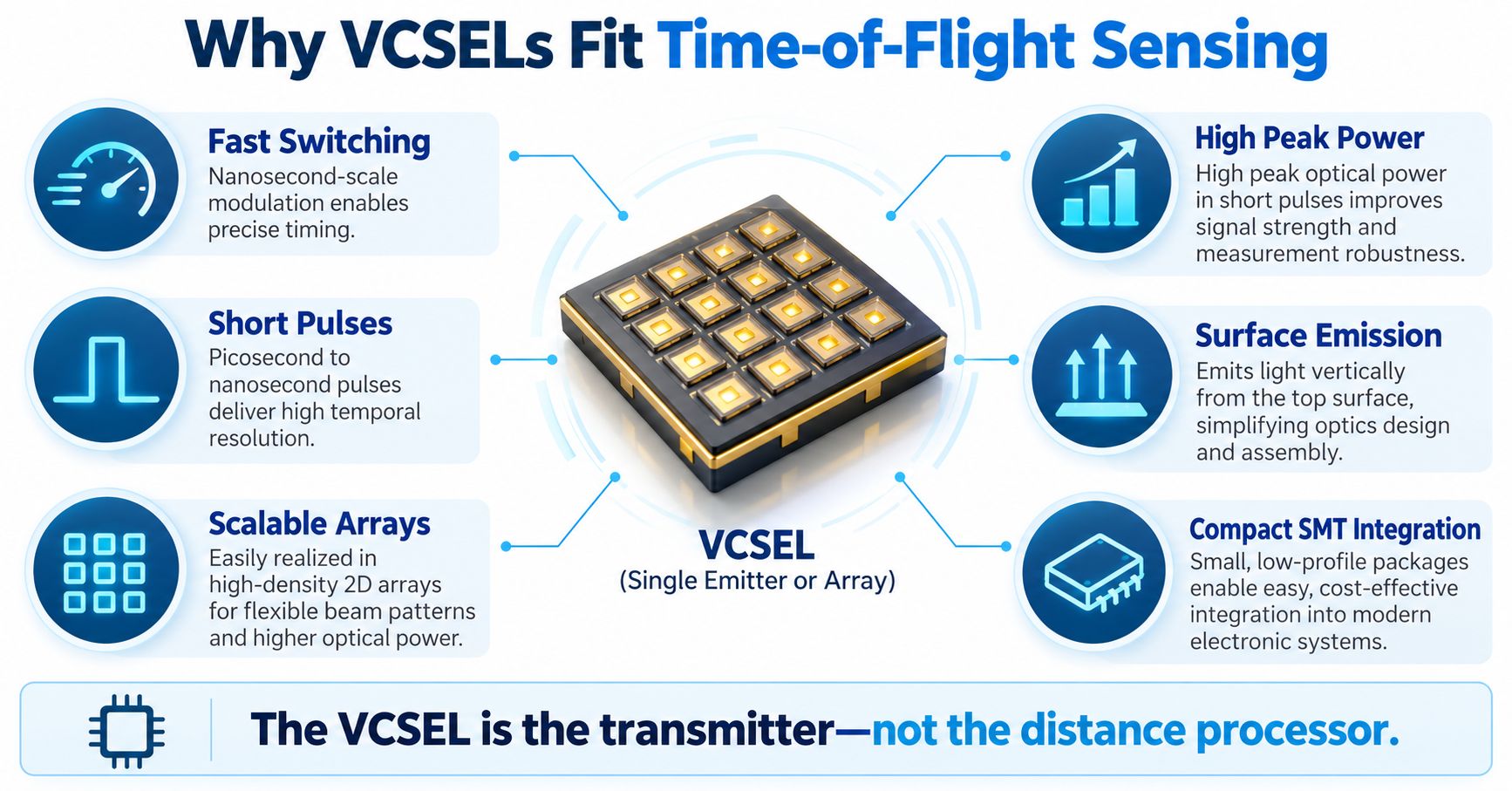
Fast Switching
dToF can require very rapid optical pulses, while iToF can require high-frequency modulation. VCSELs can support fast direct modulation because of their semiconductor structure and compact active region.
Coherent currently offers high-power 940 nm VCSEL arrays with approximately 1 ns rise time for dToF-oriented high-frequency modulation.
Short Pulses
A dToF source can transmit high peak optical power in short bursts. However, pulse width does not directly equal final system distance accuracy. Final precision also depends on SPAD timing jitter, TDC resolution, photon statistics, SNR, calibration, multipath and processing.
Scalable Arrays
VCSEL technology allows many emitters to be placed on one die:
single emitter → small array → large array
This makes VCSELs attractive for high-power scene illumination.
High Peak Power
A small single VCSEL may provide milliwatt-level power. A multi-emitter VCSEL array can reach multi-watt peak optical power.
Coherent’s current 940 nm array portfolio includes multi-watt products, and its high-power dToF family specifies up to about 5.5 W with approximately 1 ns rise time. See Coherent high-power 940 nm VCSEL arrays.
These are very different products from compact SMD single-channel VCSELs.
Surface Emission
VCSELs emit perpendicular to the wafer surface, which is useful for 2D arrays, wafer-level testing, SMD packaging and integration with diffusers or DOEs.
Compact Integration
VCSELs can be packaged in small surface-mount formats for robots, access systems, compact sensors and consumer electronics.
For packaging differences, see SMD VCSEL vs TO-Can VCSEL.
Single VCSEL vs VCSEL Array for ToF
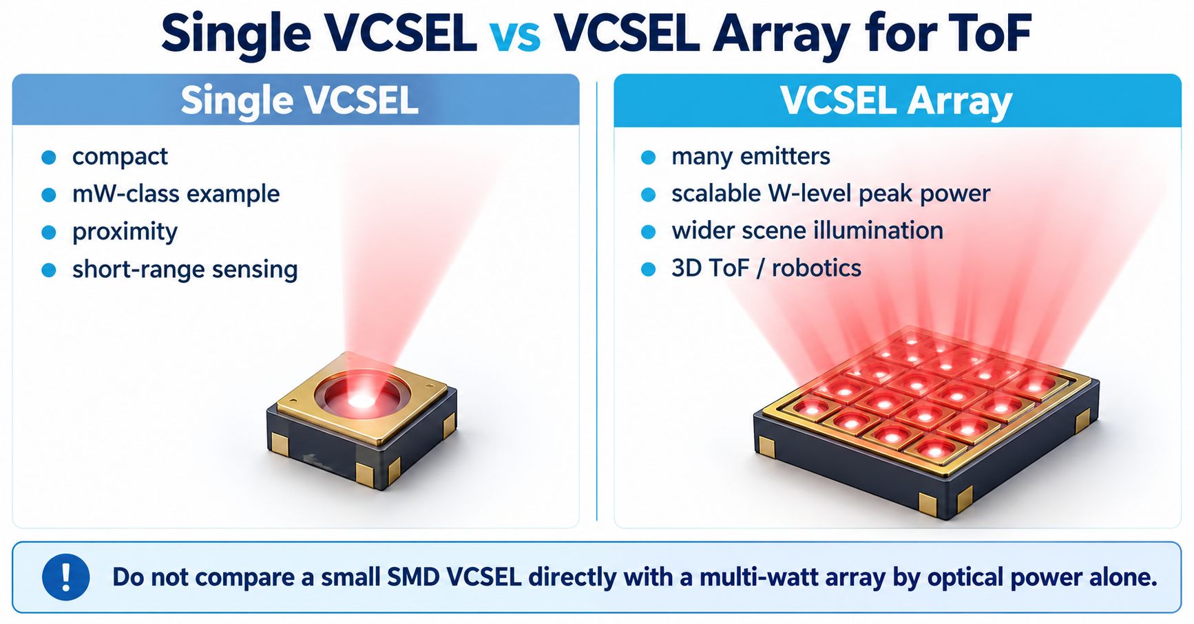
| Factor | Single / Small VCSEL | Multi-Emitter VCSEL Array |
|---|---|---|
| Typical power class | mW-class examples common | W-class peak power possible |
| Emitter count | One / few | Many |
| Footprint | Very compact | Larger die / illumination module |
| Electrical current | Lower | Higher total drive |
| Illumination | Local / narrow area | Wider scene illumination |
| Typical role | Proximity, short-range sensing | 3D ToF, robotics, depth camera |
| Optics | Simple lens possible | Diffuser / DOE / MLA common |
| Thermal design | Smaller heat load | More demanding |
A small emitter can be suitable for proximity and short-range optical sensing. An array can provide much more scene illumination for flood illumination, high-peak-power dToF, 3D cameras and robotics.
Do not compare a small SMD VCSEL directly with a multi-watt VCSEL array by optical power alone.
Flood Illumination vs Dot Projection
The VCSEL chip is only the source. External optics determine how the source illuminates the scene.
Flood Illumination
Flood illumination spreads optical power across a continuous field of illumination. Typical uses include iToF cameras, flash dToF, in-cabin sensing, gesture recognition and depth cameras.
Dot Projection
A diffractive optical element can split VCSEL light into many points. Applications include structured light, face sensing, active stereo and selected 3D sensing systems.
A dot projector is not automatically a ToF system.
Why 940 nm Is Common in ToF
940 nm has become a major wavelength in active depth sensing, not because ToF mathematically requires it, but because it combines lower solar background around the 940 nm atmospheric absorption region, minimal visible red glow and a mature VCSEL / filter / receiver ecosystem.
For the detailed wavelength comparison, see 850 nm vs 940 nm VCSEL: Which Wavelength Is Better for 3D Sensing and ToF?.
940 nm VCSEL ToF Applications
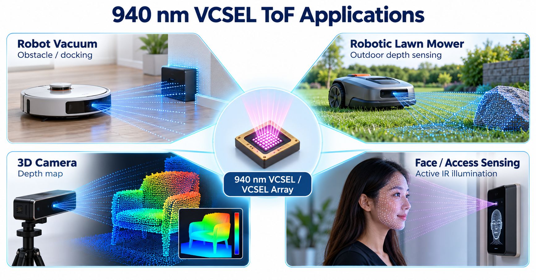
Robot Vacuum Cleaners
ToF sensing can support obstacle detection, wall ranging, docking, object distance measurement and mapping support.
A single-zone module may provide one ranging direction, while a multizone ToF device can output a small depth map.
Robotic Lawn Mowers
Outdoor robotic mowers face bright sunlight, grass, dark obstacles, wet surfaces, shadows and large temperature variation. This increases the importance of 940 nm illumination, narrow-band filtering, sufficient peak power and robust ambient-light rejection.
3D Cameras
A ToF camera can illuminate a field of view and return depth information for many pixels or zones. Applications include machine vision, human detection, gesture sensing, industrial automation and spatial mapping.
Face and Access Sensing
Active NIR illumination can provide depth information independently of visible room lighting. 940 nm is attractive because it is far less perceptible to users.
The recognition algorithm itself is not performed by the VCSEL; the VCSEL supplies the active infrared illumination.
What Determines ToF Range?
One of the most common sourcing mistakes is asking:
How many meters can a 7 mW VCSEL measure?
There is no universal answer. Range is a complete-system result.
A simplified photon budget includes:
VCSEL Power × Optical Efficiency × Target Reflectivity × Receiver Collection Efficiency × Detector PDE/QE
versus:
Distance Loss + Ambient Background + Noise
Important variables include peak power, pulse width, duty cycle, field of illumination, receiver FOV, target size, target reflectivity, lens aperture, optical filter, detector PDE, sunlight and averaging.
A 7 mW emitter used in a narrow short-range geometry solves a very different problem from a 5 W array illuminating a wide scene.
Target Reflectivity Still Matters
ToF measures time or phase rather than only reflected intensity, but returned signal strength still matters.
A black object may return fewer photons than a white object. This can affect maximum range, depth noise, confidence and measurement rate.
Optical Filters and Ambient Light
A ToF receiver normally includes a narrow-band filter around the source wavelength. The filter reduces sunlight, room lighting and unrelated infrared.
Filter design must consider VCSEL center wavelength, source tolerance, temperature shift, incidence angle and field of view.
An extremely narrow filter is not automatically better because source and filter wavelengths can shift with temperature and viewing angle.
Multipath Interference
The ideal path is:
VCSEL → Target → Receiver
Real light can follow several paths, such as:
VCSEL → Wall → Floor → Receiver
These additional paths can produce biased distance, mixed depth, false targets and depth artifacts.
Cover-Glass Crosstalk
Compact products often place the transmitter and receiver behind a shared cover window. Some transmitted light can reflect internally and reach the receiver without ever reaching the target.
This optical crosstalk can be reduced using mechanical isolation, optical baffles, coatings, calibration and crosstalk-compensation algorithms.
Peak Power vs Average Power
dToF laser specifications should clearly distinguish:
- Peak optical power
- Average optical power
- CW optical power
- Pulse width
- Repetition rate
- Duty cycle
A VCSEL array can produce high peak power while operating at a relatively low duty cycle.
For a ToF RFQ, “power” should never be specified without stating whether it means CW, average, or peak pulsed.
Rise Time and Pulse Width
Fast optical edges are valuable in dToF, but:
Pulse width or rise time is not the same as finished system distance resolution.
Final depth precision also depends on detector jitter, TDC resolution, histogram processing, photon count, SNR, calibration and multipath.
Eye Safety in ToF Systems
Neither 850 nm nor 940 nm should be called inherently eye-safe.
A finished ToF product must consider wavelength, peak power, average power, pulse duration, repetition rate, emitting aperture, divergence, diffuser / DOE, failure conditions and accessible emission.
A commercial ToF module may achieve a laser-safety classification as a complete module. That does not mean any bare VCSEL automatically has the same classification in another optical design.
ToF vs Traditional IR Proximity Sensing
Traditional reflective IR proximity sensors often infer object presence from the amount of returned light.
ToF instead measures travel time or phase, allowing it to produce a more direct distance estimate. Reflectivity still affects signal strength, but the fundamental measured quantity is different.
ToF vs LiDAR
Time-of-Flight is a distance-measurement principle. LiDAR is a broader system category for optical ranging and spatial mapping.
Many LiDAR systems use ToF, but not every small ToF proximity module is normally called LiDAR.
VCSEL is highly attractive for compact short- and medium-range array illumination, but it is not automatically the best laser architecture for every long-range LiDAR system.
VCSEL for ToF — OEM Selection Checklist
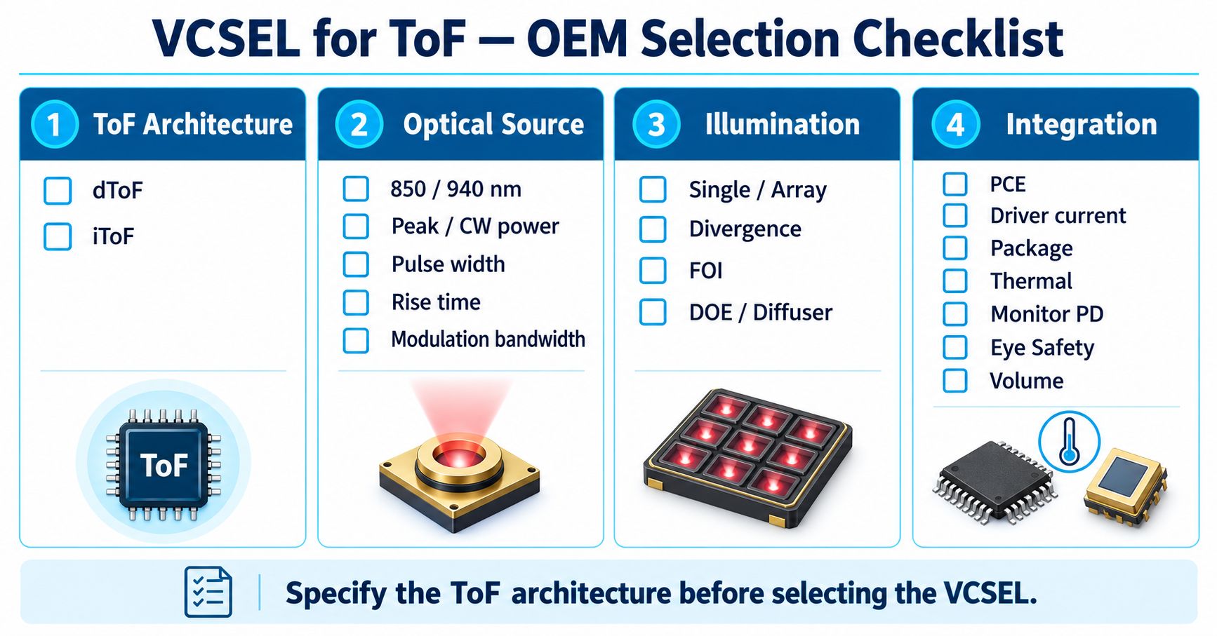
| Parameter | Why It Matters |
|---|---|
| ToF architecture | dToF vs iToF determines pulse / modulation requirements |
| Wavelength | 850 / 940 nm affects receiver and ambient-light behavior |
| Peak optical power | Critical to return photon budget |
| CW / average power | Relevant to thermal and continuous operation |
| Pulse width | Important for dToF source behavior |
| Rise / fall time | Affects fast pulse fidelity |
| Modulation bandwidth | Important for iToF and high-speed modulation |
| Emitter count | Single VCSEL vs array |
| Array geometry | Determines scalable power and illumination pattern |
| Divergence | Determines raw beam distribution |
| Field of illumination | Must match scene coverage |
| PCE | Affects electrical and thermal efficiency |
| Driver current | Defines electronics requirements |
| Package | SMD / chip / array / module integration |
| DOE / diffuser | Defines flood or patterned illumination |
| Monitor photodiode | Can support monitoring / safety architecture |
| Operating temperature | Important for robotics / industrial / automotive |
| Eye-safety requirement | Must be evaluated at module level |
| Prototype quantity | Development planning |
| Annual volume | Packaging / production strategy |
A strong RFQ starts with:
We are developing a [dToF / iToF] system at [850 / 940 nm] for [application], with a required range of [X], field of illumination of [X], and receiver architecture of [SPAD / CMOS ToF].
Lumi VCSEL Examples for ToF-Related OEM Development
Lumi currently offers compact 850 nm and 940 nm SMD VCSEL products. These are useful VCSEL building blocks, but they should not be confused with multi-watt arrays used in large-area ToF illumination.
Lumi 940 nm 1206 SMD VCSEL — 1206VCA940R8
The 940nm 1206 SMD VCSEL – 1206VCA940R8 is a compact single-channel active-sensing source.
| Parameter | Value |
|---|---|
| Center wavelength | 940 nm typ. |
| Optical power | 7.2 mW typ. |
| Operating current | 10 mA typ. |
| Forward voltage | 1.8 V typ. |
| PCE | 40% typ. |
| Package | 1206 SMD |
This device is best understood as a compact single-channel VCSEL emitter for PCB-level optical sensing, not a multi-watt ToF illumination array.
Lumi 940 nm 1616 VCSEL + Photodiode
The 940nm 1616 SMD VCSEL & Photodiode – 1616VCA940R8-PD0224-Z integrates a 940 nm VCSEL, photosensitive diode and compact 1.6 × 1.6 mm SMD package.
Current VCSEL-side values include 7.2 mW typical optical power, 10 mA typical operating current, 1.8 V typical forward voltage, 23° typical divergence and 40% typical PCE.
An integrated photodiode is not automatically a SPAD ToF receiver.
A standard photodiode does not by itself provide the single-photon timing architecture required by typical dToF systems.
Lumi 850 nm 1206 SMD VCSEL — 1206ULM850-L
The 850nm 1206 SMD VCSEL – 1206ULM850-L illustrates compact high-speed VCSEL performance.
| Parameter | Value |
|---|---|
| Typical wavelength | 850 nm |
| Optical power | 2 mW typ. @ 6 mA |
| Peak power | 30 mW specified |
| 3 dB modulation bandwidth | ≥3 GHz @ 6 mA |
| Rise / fall time | 70 ps typ., 80 ps max under stated conditions |
| Viewing angle | 12° typ. |
| Package | 1206 SMD |
The high modulation bandwidth demonstrates that VCSEL technology can support fast optical modulation. It should not be interpreted as proof that this specific device alone forms a complete ToF transmitter module.
For the current family overview, see the Lumi VCSEL Laser Diode portfolio.
Frequently Asked Questions
What does a VCSEL do in a ToF sensor?
The VCSEL is the optical transmitter. It emits infrared pulses or modulated light toward the target. The receiver detects reflected light, and timing or phase electronics calculate distance.
Does a VCSEL measure distance by itself?
No. A VCSEL produces the optical signal. Distance measurement requires a receiver plus timing or phase-processing electronics.
What is the difference between dToF and iToF?
dToF measures photon travel time directly, commonly using short pulses, SPADs and TDCs. iToF measures the phase shift of modulated illumination, commonly using CMOS ToF pixel arrays.
Can both dToF and iToF use VCSELs?
Yes. dToF can use short pulsed VCSEL illumination, while iToF can use high-frequency modulated VCSEL illumination.
Why are VCSELs used in ToF?
VCSELs support fast switching, compact integration, scalable arrays, high peak power in array form and high-volume semiconductor manufacturing.
Why is 940 nm common in ToF sensing?
940 nm offers favorable outdoor ambient-light conditions, low visible glow and a mature ecosystem of VCSEL arrays, filters and ToF receivers.
What is a SPAD?
SPAD stands for Single-Photon Avalanche Diode. It is a highly sensitive detector architecture capable of registering photon events with precise timing.
What is a ToF histogram?
A ToF histogram counts detected photon events by arrival time. Target-reflected photons tend to form a timing peak while background photons are more broadly distributed.
Is a photodiode the same as a SPAD?
No. A SPAD is a specialized avalanche detector designed for single-photon detection and timing. A standard photodiode does not automatically provide dToF timing capability.
Does more VCSEL power always mean longer ToF range?
No. Range depends on the complete photon budget, including field of illumination, target reflectivity, receiver aperture, detector efficiency, ambient light and signal processing.
Is a 940 nm VCSEL eye-safe?
Not automatically. Eye safety depends on the finished optical system, including power, pulse conditions, divergence, optics, aperture and failure modes.
Can a small 7 mW VCSEL be used for ToF?
Potentially for an appropriately designed short-range or compact optical system, but achievable range cannot be determined from the 7 mW figure alone.
Which parameters should I provide when requesting a VCSEL for ToF?
Provide the ToF architecture, wavelength, target range, field of illumination, receiver type, peak/CW power requirement, pulse or modulation conditions, package, operating temperature, safety requirement and expected production volume.
Start with the ToF Architecture, Then Select the VCSEL
A reliable VCSEL selection process begins with the sensing architecture.
For direct ToF:
Required Range → Photon Budget → Wavelength → Peak Power → Pulse Width / Rise Time → Single or Array → Illumination Optics → SPAD Receiver
For indirect ToF:
Required Depth Range → Modulation Frequency → Wavelength → VCSEL Bandwidth → Optical Power → FOI → CMOS ToF Receiver
Then evaluate:
Package → Driver → Thermal Design → Optical Filter → Eye Safety → Production Volume
The VCSEL is a critical component, but it is only one part of the complete ranging system.
The most useful way to think about ToF is:
VCSEL emits → Scene reflects → Receiver detects → Electronics measure → Algorithm calculates distance
Lumi currently supports compact 850 nm and 940 nm SMD VCSEL components for OEM optical sensing and high-speed optoelectronic development.
For a ToF, robotics, proximity or 3D-sensing project, provide the intended architecture, wavelength, target range, field of illumination, receiver type, drive conditions and production volume so the VCSEL can be evaluated against the complete optical system.
