

Choosing a laser diode should begin with the optical job the system must perform—not with the highest available power, the most familiar wavelength, or the most sophisticated package.
A practical OEM selection sequence is:
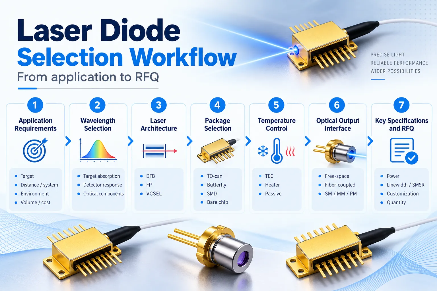
Application → Wavelength → Laser Architecture → Operating Mode → Package → Temperature Control → Optical Output → Critical Parameters → RFQ
This order matters because several laser diodes can share the same nominal wavelength while behaving very differently in a real system. A 1550 nm FP laser, a 1550 nm DFB laser and a fiber-coupled 1550 nm DFB module may all emit near the same wavelength, yet differ in spectral behavior, tuning, packaging, thermal control, optical interface and intended application.
The same distinction applies to terminology:
- DFB / FP / VCSEL describe the laser architecture.
- TO-can / Butterfly / SMD / chip-on-submount describe package formats.
- Free-space / fiber-coupled describe the optical output interface.
- TEC / heater / passive thermal design describe temperature-management approaches.
- CW / pulsed / QCW describe operating modes.
These categories can be combined. A DFB laser can be packaged in a TO-can or butterfly housing. A TO-can can provide free-space output or a fiber pigtail. A VCSEL can be placed in an SMD package. A butterfly package may integrate a TEC, thermistor, monitor photodiode and fiber.
That is why the right question is not simply:
Which laser diode is best?
The useful question is:
Which laser diode gives my system the required wavelength, optical behavior, thermal stability and integration interface with the lowest total system complexity?
Lumi organizes its laser diode portfolio around these same selection dimensions so engineers can move from architecture to package and optical interface without treating them as interchangeable categories.
Start with the Application Requirements
Before comparing datasheets, define what the laser must actually do.
A gas-sensing laser and a 3D-sensing VCSEL may both be semiconductor lasers, but their critical specifications are completely different. The gas-sensing project may depend on wavelength accuracy, spectral purity and controlled tuning. The 3D-sensing project may depend more on pulse behavior, array format, wavelength, field of illumination and receiver compatibility.
The first engineering questions should therefore be application-level questions.
What Is the Optical Task?
Examples include:
- TDLAS gas sensing
- Optical communication
- 3D sensing and Time-of-Flight
- Proximity sensing
- Optical ranging
- Precision measurement
- General OEM illumination or transmission
- Industrial instrumentation
- Pumping or excitation
Each task defines a different priority.
For TDLAS, wavelength and spectral behavior are central. For short-reach datacom, modulation and fiber compatibility may dominate. For ToF, pulse or modulation behavior, wavelength and receiver response are critical. For general optical instrumentation, package, beam, output power and cost may matter more than narrow linewidth.
What Does the Laser Interact With?
Identify the target medium or receiving element:
- Molecular absorption line
- Optical fiber
- Silicon detector
- InGaAs detector
- Photodiode
- SPAD / ToF receiver
- Optical filter
- Grating or wavelength-sensitive optical element
- Free-space target
This immediately narrows the wavelength and architecture choices.
What Are the Environmental Limits?
Define:
- Minimum ambient temperature
- Maximum ambient temperature
- Available heat sinking
- Power budget
- Vibration / mechanical constraints
- Package volume
- Optical alignment tolerance
A laser that performs correctly on a laboratory bench may require a different package or thermal-control strategy inside an outdoor instrument.
What Is the Production Model?
Also define:
- Prototype quantity
- Expected annual volume
- Standard or custom wavelength
- Required screening
- Connector and fiber customization
- Mechanical customization
- Qualification requirements
A bare chip can make sense for a photonics manufacturer with die-attach and alignment capability, while a fiber-pigtailed butterfly device can reduce integration work for an OEM that wants a pre-aligned optical source.
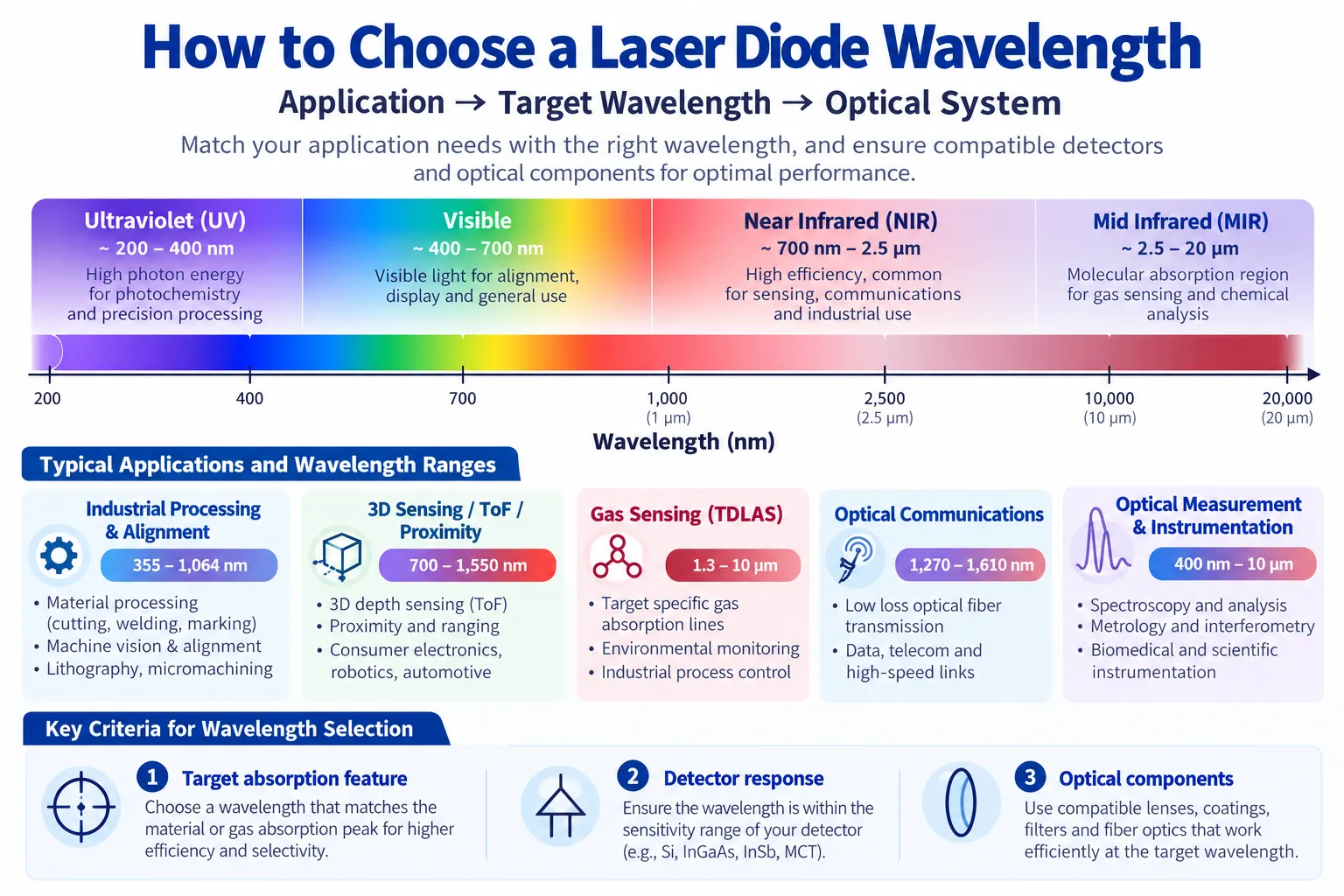
Step 1 — Choose the Right Laser Diode Wavelength
Wavelength is usually the first optical specification engineers think about, but a nominal wavelength is only the beginning.
The correct wavelength depends on what the light must interact with.
Gas Sensing and TDLAS
For TDLAS, the target wavelength is selected from a molecular absorption feature.
The correct sequence is:
Target gas → absorption spectrum → candidate transition → interference analysis → pressure / temperature → required laser tuning window
This is why a gas cannot normally be reduced to one universal wavelength.
For example, methane has multiple useful absorption features. A system using a 1653.7 nm methane DFB is targeting a specific near-infrared region; another design may use a different methane line because the detector, interference environment or concentration range is different.
For a deeper gas-sensing workflow, see the TDLAS Laser Diode Wavelength Guide.
Optical Communication
Communication wavelength selection depends on:
- Fiber type
- Link distance
- Fiber loss
- dispersion
- receiver sensitivity
- system architecture
- wavelength-channel plan
Common semiconductor laser directions include 850 nm for short-reach multimode-fiber systems and 1310 / 1550 nm-class devices for other optical communication architectures.
The wavelength should be selected together with the actual fiber and receiver rather than independently.
3D Sensing and ToF
In active sensing, wavelength affects both transmitter and receiver performance.
For example, 850 nm and 940 nm VCSEL systems can both support optical sensing, but the trade-off changes because silicon detector sensitivity and outdoor solar background differ by wavelength.
For the detailed comparison, see 850 nm vs 940 nm VCSEL for 3D Sensing and ToF.
Wavelength Must Match the Complete Optical System
Check compatibility with:
- Detector spectral response
- Fiber transmission
- Bandpass filters
- Lens coatings
- mirrors
- diffusers / DOE
- optical isolators
- wavelength-sensitive components
A wavelength that is ideal for the emitter but poorly matched to the receiver or optics can produce a weak system.
Center Wavelength Is Not the Same as Usable Range
A datasheet may state:
Center wavelength: 1653.7 nm
But an engineer may actually need to know:
- At what temperature is that wavelength specified?
- At what current?
- What is the unit-to-unit tolerance?
- How much can current tune it?
- How much can temperature tune it?
- Does the full operating window cross the required target line?
For spectroscopy and wavelength-sensitive applications, the usable tuning range is often more important than the nominal wavelength printed in a model name.
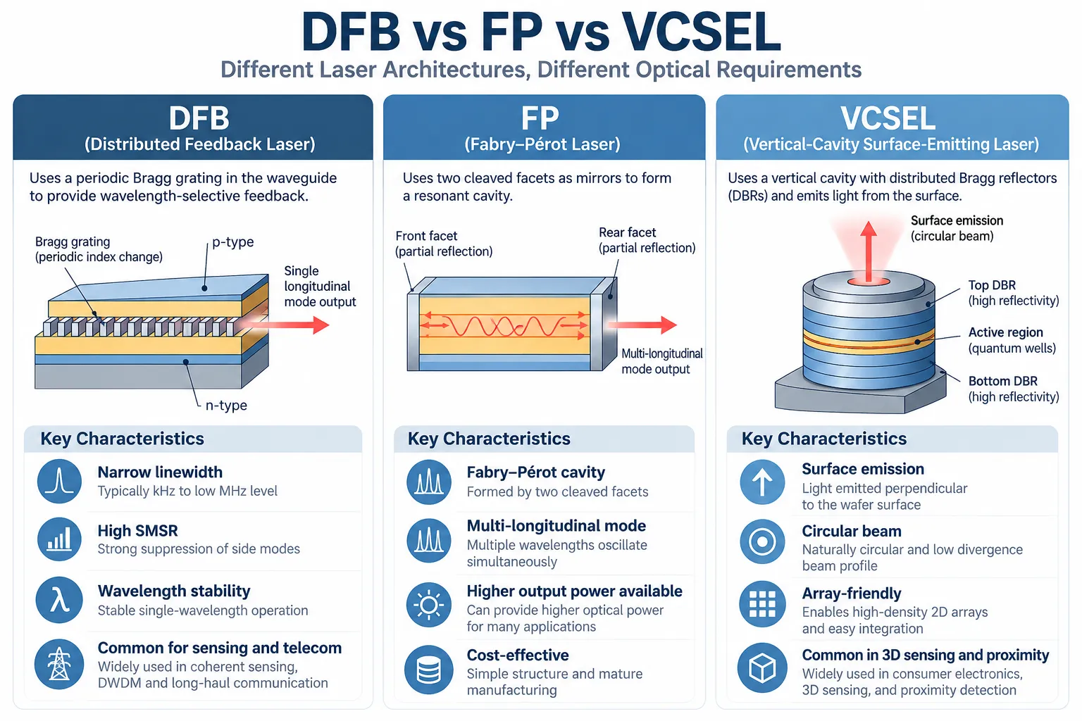
Step 2 — Choose Between DFB, FP and VCSEL
DFB, FP and VCSEL are three laser architectures that solve different optical problems.
There is no universal ranking such as:
DFB > VCSEL > FP
The best architecture is the one whose optical behavior matches the application.
| Selection Factor | DFB | FP | VCSEL |
|---|---|---|---|
| Basic architecture | Distributed wavelength-selective feedback | Fabry–Pérot facet cavity | Vertical cavity with surface emission |
| Spectral behavior | Strong wavelength selection; often used for single-longitudinal-mode applications | Multiple longitudinal modes are common | Depends on emitter design; surface-emitting architecture |
| Strong selection reason | Wavelength control, spectral selectivity, sensing / telecom | Practical optical source when strict spectral control is unnecessary | Compact surface emission, arrays, short-reach links and active sensing |
| Typical OEM questions | Wavelength, SMSR, linewidth, tuning | Power, spectrum, operating mode, beam | Wavelength, emitter size / array, modulation, divergence |
| Common Lumi directions | TDLAS, sensing, telecom, precision photonics | General optical systems and selected ranging / instrumentation | 795 / 850 / 940 nm sensing and compact integration |
For the full architecture comparison, see DFB vs FP vs VCSEL: Laser Diode Types Compared.
When to Choose a DFB Laser Diode
A DFB laser includes wavelength-selective distributed feedback, commonly implemented through a grating structure.
Consider DFB when the system depends on:
- Narrow and controlled spectral output
- Strong side-mode suppression
- Stable target wavelength
- Current and temperature tuning
- TDLAS absorption-line matching
- wavelength-channel control
- coherent or precision photonics requirements
However, DFB does not automatically mean “ultra-narrow linewidth.” The actual linewidth can differ substantially among DFB products, and a narrow-linewidth coherent application may require specifications beyond the architecture name.
For current product directions, see Lumi DFB Laser Diodes.
When to Choose an FP Laser Diode
A conventional FP laser uses the chip facets to form a Fabry–Pérot cavity.
FP can be a strong choice when:
- The detector has a broad spectral response
- Multiple longitudinal modes are acceptable
- Strict wavelength selectivity is not required
- Practical optical output and cost matter more than single-frequency behavior
- A conventional edge-emitting source fits the system optics
The engineering principle is important:
Do not pay for spectral control if the optical system gains no value from it.
For available directions, see Lumi FP Laser Diodes.
When to Choose a VCSEL
VCSEL stands for Vertical-Cavity Surface-Emitting Laser.
The light exits perpendicular to the wafer rather than from a cleaved edge. This makes the architecture especially attractive for:
- Compact SMD integration
- Dense emitter arrays
- 3D sensing
- Proximity sensing
- ToF illumination
- Short-reach optical communication
- High-volume semiconductor assembly
VCSEL selection should include:
- Wavelength
- Single emitter or array
- Optical power or peak power
- Modulation behavior
- aperture / emitter geometry
- divergence
- far-field pattern
- package
For current products and sensing directions, see Lumi VCSEL Laser Diodes.
Step 3 — Define CW, Pulsed or QCW Operation
Architecture and wavelength are not enough. The operating mode changes how optical power, driver current and thermal load should be interpreted.
Continuous-Wave — CW
CW means the laser is operated continuously under its specified conditions.
Important parameters include:
- CW optical output power
- Operating current
- Forward voltage
- wall-plug or power-conversion efficiency
- junction / case temperature
- heat sinking
- long-term stability
CW is common in continuous optical transmission, spectroscopy, instrumentation and many sensing systems.
Pulsed Operation
A pulsed laser delivers optical energy during short time intervals.
Key specifications include:
- Peak optical power
- Pulse width
- Rise and fall time
- Repetition rate
- Duty cycle
- pulse-current limit
- thermal constraints
A high peak-power value should never be compared directly with a CW power value without considering the pulse conditions.
QCW — Quasi-Continuous-Wave
QCW generally uses pulses longer than ultra-short ranging pulses but with a limited duty cycle so the laser can operate at higher instantaneous power while managing average thermal load.
When evaluating a QCW product, always check:
- Pulse width
- duty cycle
- repetition
- peak / pulsed power
- drive current
- temperature
A device specified at a 10 µs pulse width should not automatically be treated as suitable for a nanosecond dToF system.
Peak Power vs Average Power
A common RFQ mistake is:
“We need a 100 W laser.”
That statement is incomplete.
The supplier needs to know whether the customer means:
- 100 W CW
- 100 W peak pulsed
- 100 W at a specific duty cycle
- 100 W before or after fiber coupling
- 100 W from one emitter or an array
Operating mode is part of the optical-power specification.
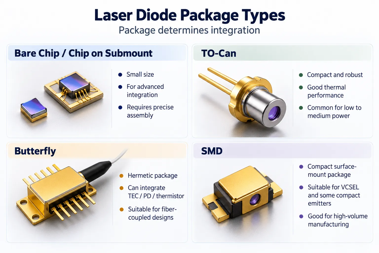
Step 4 — Select the Package
A laser diode package is not just a protective shell. It affects mechanical mounting, electrical connection, heat flow, optical alignment and the amount of work the OEM must perform.
Common integration forms include:
- Bare chip / chip-on-submount
- TO-can
- Butterfly
- SMD
- Application-specific modules
For a deeper explanation, see Laser Diode Package Types: TO-Can, Butterfly, SMD & Fiber.
Bare Chip / Chip-on-Submount
A bare or submounted laser can be attractive when the OEM controls:
- Die attach
- wire bonding
- optics
- thermal design
- alignment
- package assembly
Advantages include:
- Maximum integration freedom
- Small source footprint
- Custom module design
But it moves significant responsibility to the OEM.
Consider bare die when the project is being integrated by an experienced photonics manufacturer or module builder rather than a team looking for a drop-in optical source.
TO-Can
TO-can packages are compact metal optoelectronic packages.
Depending on the design, a TO laser may include:
- Window or lens
- Monitor photodiode
- thermistor
- heater
- TEC
- fiber pigtail
TO is a good starting point when compact size and established mechanical integration are important.
It is incorrect to assume:
TO-can = free-space only
or:
TO-can = no TEC
Different TO designs can support different functions.
Explore current Lumi TO-Can Laser Diodes.
Butterfly Package
Butterfly packages provide more internal integration space.
They can integrate:
- Laser chip
- TEC
- thermistor
- monitor photodiode
- coupling optics
- optical isolator
- fiber pigtail
- multiple electrical control pins
Butterfly is therefore a strong option when the system benefits from stable fiber output and integrated thermal control.
The trade-offs are:
- Larger package
- More electrical connections
- Higher component complexity
- TEC controller requirement
- Fiber handling
Explore Lumi Butterfly Laser Diodes.
SMD Package
SMD describes a surface-mount package for PCB assembly.
It does not define the laser architecture.
A VCSEL can be packaged in SMD form, which makes it attractive for:
- Automated placement
- Compact sensing modules
- High-volume assembly
- Consumer and industrial electronics
The correct distinction is:
VCSEL = architecture
SMD = package
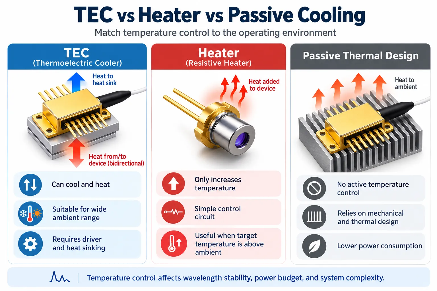
Step 5 — Decide Whether Temperature Control Is Needed
Laser-diode wavelength, output power and reliability depend on temperature.
The correct thermal strategy depends on how much the optical system can tolerate.
Passive Thermal Design
Some systems can operate with:
- Heat sink
- metal package
- PCB copper
- airflow
- chassis conduction
without actively forcing the laser to a specific temperature.
Passive thermal design reduces control complexity but does not provide precise setpoint regulation.
It can be appropriate when:
- Wavelength tolerance is relatively wide
- ambient range is controlled
- power is modest
- thermal drift is acceptable
Resistive Heater
A heater adds thermal energy.
It can be useful when the laser needs to operate at a target temperature above the surrounding environment.
Advantages can include:
- Simple heating mechanism
- lower control complexity than a bidirectional TEC system in some designs
- useful wavelength-positioning strategy in selected DFB products
But a heater cannot actively cool the laser below the ambient temperature.
TEC — Thermoelectric Cooler
A TEC transfers heat through the thermoelectric effect.
With the appropriate controller, a TEC system can actively:
- Cool
- Heat
- maintain a controlled setpoint
This makes TEC attractive when:
- The target temperature may be above or below ambient
- Wavelength stability is important
- the ambient range is broad
- repeatability matters
- the laser tuning strategy depends on chip temperature
However, TEC does not remove the need for system heat sinking.
The TEC pumps heat from one side to the other, and the rejected heat plus electrical losses must still be removed from the package.
TEC Is Not Automatically the Best Choice
TEC adds:
- Electrical power
- control electronics
- heat rejection requirements
- package complexity
If the application tolerates thermal drift or only needs controlled heating above ambient, another approach may be more efficient.
The correct question is:
What junction or package temperature range must the laser maintain for the optical requirement?
Then select the thermal-control method.
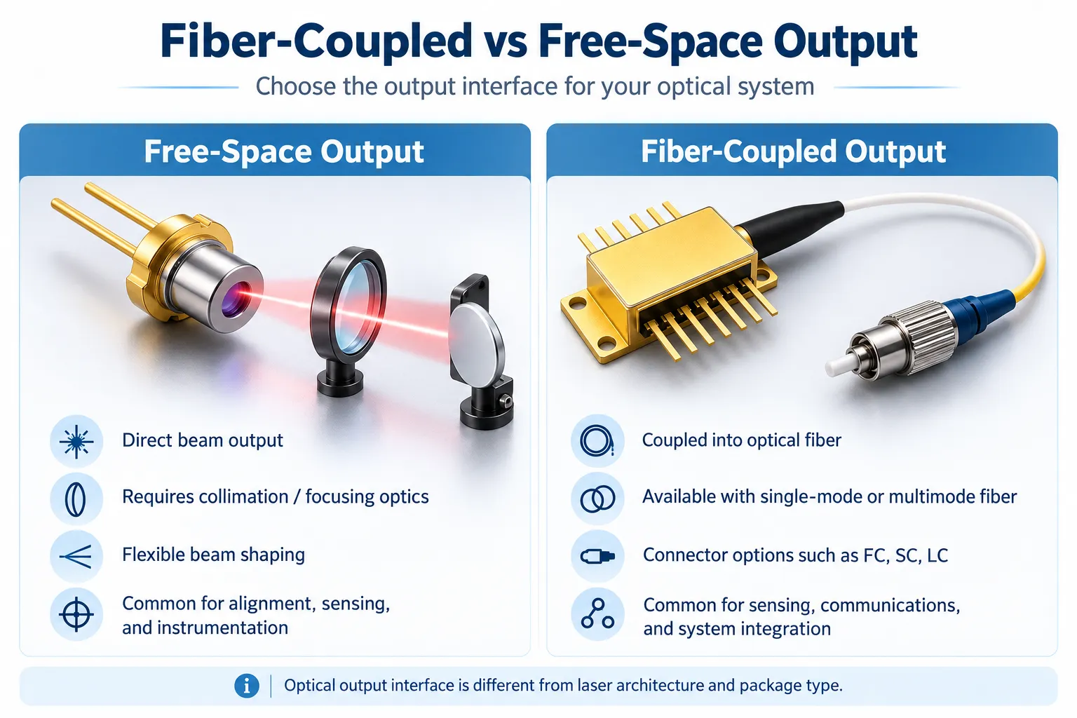
Step 6 — Choose Free-Space or Fiber-Coupled Output
Free-space and fiber-coupled describe how the light leaves the source and enters the next part of the optical system.
They are not laser architectures.
For the full guide, see Fiber-Coupled Laser Diode: Pigtailed vs Free-Space Output.
Free-Space Output
Free-space is attractive when:
- The laser and optical system are close together
- OEM engineers need direct access to the beam
- Custom collimation / focusing is required
- Beam shaping is part of the product design
- Avoiding source-to-fiber coupling loss is important
But the OEM may need to manage:
- Collimation
- focusing
- mechanical alignment
- beam position
- optical cleanliness
- vibration tolerance
Fiber-Coupled Output
Fiber coupling moves more optical alignment into the source assembly.
It can simplify systems that use:
- Fiber delivery
- remote optical heads
- compact sensing cells
- optical splitters
- telecom components
- modular photonics
Important fiber specifications include:
- SM / MM / PM fiber
- fiber core
- numerical aperture
- mode-field diameter where relevant
- connector type
- fiber length
- polarization requirements
- optical power at the fiber output
- return reflection
- bend limitations
SM, MM and PM Fiber Are Not Interchangeable
Single-mode fiber supports a restricted spatial mode and is important where beam quality and coherent / wavelength-specific fiber systems matter.
Multimode fiber supports multiple propagation modes and can accept a larger optical étendue, depending on the source and coupling design.
Polarization-maintaining fiber is used when maintaining a defined polarization state is important.
Do not request only:
“Fiber coupled.”
Specify the fiber that the receiving optical system expects.
Power Must Be Defined at the Measurement Point
For a fiber-coupled laser, ask whether the specified power is measured:
- At the laser chip
- Inside the package
- At the fiber pigtail
- After the connector
For an OEM system, fiber-end power is often the most practical value because it represents the light actually delivered to the next subsystem.
Explore current Lumi Fiber-Coupled Laser Diodes.
Step 7 — Verify the Critical Datasheet Parameters
After the architecture and integration format are selected, compare actual products using the parameters that matter to the application.
| Parameter | What the Engineer Should Confirm |
|---|---|
| Center wavelength | Under what current and temperature is it specified? |
| Wavelength tolerance | What is the allowed unit-to-unit and production variation? |
| Tuning range | Can current and temperature reach the required operating wavelength? |
| Optical output power | CW, peak, QCW, package output or fiber-end power? |
| Operating current | Can the planned driver supply it with required stability? |
| Forward voltage | What electrical power and driver headroom are required? |
| Linewidth | Does the actual linewidth meet the spectroscopy / coherent-system need? |
| SMSR | Is side-mode suppression important to the application? |
| Spectrum | Single longitudinal mode, multimode or application-specific? |
| Beam divergence | What collimation or focusing optics are needed? |
| Beam profile | Does the far field match the optical design? |
| Modulation bandwidth | Is the source fast enough for the link or sensing method? |
| Rise / fall time | Important for pulsed systems and fast optical switching |
| Pulse width / duty cycle | Required for pulsed and QCW sources |
| Operating temperature | Does the laser meet the environment without excessive control burden? |
| TEC / thermistor / heater | Which thermal-control functions are included? |
| Monitor photodiode | Is optical power monitoring required? |
| Package and pinout | Does it fit the PCB, driver and mechanical assembly? |
| Fiber type | SM / MM / PM and relevant fiber parameters |
| Connector | FC/APC, FC/PC, SC, LC or custom requirement |
| Reliability | What qualification, screening or life data are available for the project? |
Compare Parameters Under the Same Conditions
A frequent mistake is comparing two products whose headline specifications were measured under different conditions.
For example:
- CW power vs pulsed power
- Chip power vs fiber-end power
- 25°C wavelength vs controlled junction temperature
- typical value vs minimum guaranteed value
- short-pulse peak power vs steady-state output
The measurement condition is part of the specification.
Step 8 — Prepare a Complete OEM Laser Diode RFQ
A precise RFQ can shorten technical evaluation dramatically.
Instead of sending:
Need 1550 nm laser diode, please quote.
send the information that defines the optical system.
Application
State what the laser will do.
Examples:
- CH₄ TDLAS
- 3D ToF
- short-reach optical communication
- optical ranging
- instrumentation
Wavelength
Provide:
- Target wavelength
- acceptable tolerance
- target absorption line if spectroscopy is involved
- required tuning span
Optical Power and Operating Mode
Define:
- CW / pulsed / QCW
- output power
- peak power if pulsed
- pulse width
- repetition rate
- duty cycle
Spectral Requirements
As applicable:
- Linewidth
- SMSR
- single-mode requirement
- wavelength stability
- tuning behavior
Modulation Requirements
For high-speed or sensing systems:
- modulation bandwidth
- rise/fall time
- chirp behavior if relevant
- driver current / waveform
Thermal Requirements
Provide:
- Minimum ambient temperature
- maximum ambient temperature
- required laser setpoint
- TEC / heater preference
- power budget
- heat-sink constraints
Package and Optical Interface
Specify:
- Bare chip / submount / TO / butterfly / SMD
- Free-space / fiber
- SM / MM / PM
- Connector
- fiber length
- polarization
- pinout / mechanical constraints
Commercial Requirements
Also include:
- Prototype quantity
- expected annual volume
- required customization
- qualification or screening
- target schedule
The supplier can then evaluate the correct product platform rather than guessing from wavelength alone.
A Practical Laser Diode Selection Decision Tree
A simple decision tree can accelerate the first technical discussion.
Does the Application Require a Specific Molecular Absorption Line or Wavelength Channel?
If yes, begin with:
DFB / wavelength-selective source evaluation
Then confirm tuning, SMSR, linewidth, package and thermal control.
Is Compact Surface Emission, an Array or Active 3D Sensing Central to the System?
If yes, evaluate:
VCSEL
Then confirm wavelength, emitter configuration, optical power, modulation, divergence and package.
Can the System Accept a Conventional Edge-Emitting Source Without Tight Spectral Control?
If yes, evaluate:
FP
Then confirm output power, spectrum, package and operating mode.
Does the Optical Path Already Use Fiber?
If yes, determine whether factory fiber coupling will reduce:
- alignment risk
- assembly time
- field instability
Then select:
SM / MM / PM + connector + fiber-end power requirement
Does the Target Wavelength Need Active Thermal Stabilization?
If yes, define whether the system needs:
- heating only
- bidirectional temperature regulation
- TEC + thermistor
- external temperature controller
Is the System Pulsed?
If yes, stop comparing only CW datasheet values.
Define:
- Peak power
- pulse width
- repetition
- duty cycle
- rise/fall time
- thermal limit
Example Selection Paths
The following examples show how the same decision framework leads to different source types.
Example 1 — Methane TDLAS Analyzer
Application: CH₄ measurement
Wavelength: selected methane absorption feature
Architecture: DFB
Operating mode: wavelength scanning / modulation
Package: TO or butterfly
Temperature: TEC or application-specific temperature control
Output: free-space or SM fiber
Critical parameters: tuning range, SMSR, linewidth, optical power, temperature coefficient
This is why TDLAS selection starts from spectroscopy rather than maximum optical power.
Example 2 — 940 nm ToF Module
Application: short-range depth sensing
Wavelength: 940 nm
Architecture: VCSEL
Operating mode: pulsed or modulated according to the ToF architecture
Package: SMD / array / module
Temperature: system thermal design
Output: free-space illumination
Critical parameters: optical power, pulse or modulation behavior, divergence / FOI, PCE and receiver compatibility
See How VCSELs Work in Time-of-Flight Sensing.
Example 3 — 1550 nm Fiber Optical Source
Application: communication / measurement
Wavelength: 1550 nm class
Architecture: FP or DFB depending spectral requirements
Package: TO or butterfly
Temperature: defined by wavelength stability and environment
Output: SM or PM fiber as required
Critical parameters: fiber-end power, linewidth / spectrum, SMSR where relevant, connector, polarization and temperature stability
A nominal 1550 nm requirement is therefore not enough to choose between an FP TO device and a narrow-linewidth DFB butterfly assembly.
Common Laser Diode Selection Mistakes
Mistake 1 — Choosing by Wavelength and Power Only
Two devices with the same wavelength and power may have incompatible spectra, beam characteristics, operating modes or packages.
Mistake 2 — Treating DFB, Butterfly and Fiber-Coupled as Competing Types
They describe different dimensions.
A device can be:
DFB + Butterfly + PM Fiber + TEC
all at the same time.
Mistake 3 — Assuming the Narrowest Linewidth Is Always Better
If the system does not need spectral precision, a narrower-linewidth source may add cost and control complexity without improving the finished product.
Mistake 4 — Ignoring the Detector
The best source is not independent from the receiver.
Detector sensitivity, filter bandwidth and optical-system response can change the optimum wavelength and power requirement.
Mistake 5 — Comparing Peak Power to CW Power
Always compare power under the correct operating conditions.
Mistake 6 — Ignoring Wavelength Shift with Temperature and Current
This can be especially serious in spectroscopy and narrow optical-filter systems.
Mistake 7 — Assuming TEC Eliminates Thermal Design
A TEC moves heat. The system still needs to remove the total heat load.
Mistake 8 — Asking for “Fiber-Coupled” Without Fiber Specifications
SM, MM and PM fibers serve different optical requirements.
Mistake 9 — Assuming a Package Defines the Internal Laser
A TO-can may contain FP or DFB architecture, and SMD does not automatically mean VCSEL.
Mistake 10 — Selecting from a Marketing Table Without Checking the Datasheet
Use comparison tables to narrow the field, then validate the actual device specification and test conditions.
How Lumi Organizes Laser Diode Selection
Lumi’s product structure separates architecture from package and optical interface.
Select by Architecture
- DFB Laser Diodes for wavelength-selective sensing, communication and precision photonics.
- FP Laser Diodes for practical edge-emitting optical-source applications.
- VCSEL Laser Diodes for compact sensing, 3D recognition, proximity and short-reach photonics.
Select by Package or Interface
- TO-Can Laser Diodes for compact OEM integration.
- Butterfly Laser Diodes for higher integration of temperature control, monitoring and fiber.
- Fiber-Coupled Laser Diodes when the optical system benefits from factory-aligned fiber delivery.
The goal is not to force every customer into the most complex source. The goal is to match the source architecture, package and interface to the optical system.
Frequently Asked Questions
How do I choose the right laser diode wavelength?
Start with the application, target medium, detector and optical system. For spectroscopy, identify the target absorption transition and required tuning range. For communication, match the wavelength to the fiber and receiver. For active sensing, evaluate the transmitter wavelength together with detector sensitivity and ambient-light conditions.
What is the difference between DFB, FP and VCSEL laser diodes?
DFB, FP and VCSEL are laser architectures. DFB uses wavelength-selective distributed feedback, FP uses a Fabry–Pérot cavity commonly supporting multiple longitudinal modes, and VCSEL uses a vertical cavity with surface emission.
Does laser diode package type affect optical performance?
Yes. The package can affect temperature control, heat flow, optical alignment, fiber coupling, mechanical stability, monitor functions and available electrical interfaces. However, package type does not by itself determine the internal laser architecture.
Should I choose a TO-can or butterfly laser diode?
Choose based on integration requirements. TO packages are compact and flexible. Butterfly packages provide more space for integrated TEC, thermistor, monitor photodiode, fiber and optical functions. Neither is universally better.
When do I need a TEC-cooled laser diode?
A TEC is worth considering when the required laser operating temperature may be above or below ambient, when wavelength stability is important, or when the product operates across a broad environmental range. The system still needs suitable heat rejection and a TEC controller.
Should I choose a fiber-coupled or free-space laser diode?
Choose fiber coupling when stable delivery through fiber simplifies the optical architecture or reduces alignment burden. Choose free-space output when the OEM needs direct beam access, custom beam shaping, close source-to-optics integration or wants to avoid fiber-coupling loss.
What specifications should I include in an OEM laser diode RFQ?
Include the application, wavelength, optical power, CW/pulsed/QCW mode, spectral requirements, modulation or pulse conditions, ambient temperature, thermal control, package, fiber/free-space output, connector, prototype quantity, annual volume and any customization requirements.
Choose the Optical System First, Then the Laser Diode
The most reliable laser-diode selection process is:
Application → Wavelength → Architecture → Operating Mode → Package → Temperature Control → Optical Output → Datasheet Verification → RFQ
This avoids several common purchasing mistakes.
It prevents a butterfly package from being confused with a laser architecture. It prevents a fiber-coupled product from being treated as a fourth laser type beside DFB, FP and VCSEL. It prevents a high peak-power pulsed device from being compared directly with CW output. And it forces the wavelength, detector and thermal design to be considered as one optical system.
For an OEM project, send Lumi the actual application and system requirements rather than only a wavelength and power target. Lumi can then evaluate the appropriate DFB, FP or VCSEL architecture, TO / butterfly / SMD package direction, fiber interface, temperature-control functions and customization options.
