
16×16 & 32×32 AWGR Equipment for Optical Systems
Lumi AWGR equipment provides C-band, 100 GHz cyclic wavelength routing in a 484 × 250 × 45 mm enclosure for optical network deployment, multiport test systems and rack-oriented photonic platforms.
Choose 16×16 or 32×32 optical routing according to port density, optical-loss allowance and equipment integration requirements. AWGR equipment delivers wavelength routing—it is not a complete packet-switching appliance.
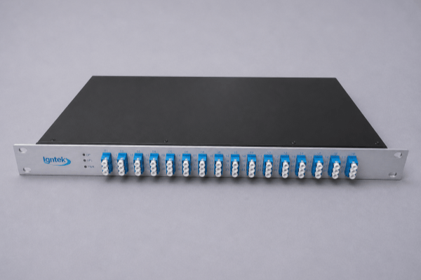
What Is AWGR Equipment?
AWGR equipment encloses a multi-input/multi-output arrayed-waveguide routing device in a larger mechanical assembly than a module. The enclosure supports easier connection to optical ports and reduces the amount of surrounding mechanical design needed in system or laboratory settings.
The optical routing mechanism remains passive and wavelength-dependent. Channel selection or higher-level switching decisions occur in external transmitters and network electronics.
- Structured multi-port optical interface
- 16×16 and 32×32 C-band configurations
- Useful for optical-system integration and laboratory platforms
- Requires an external transmitter wavelength plan and link budget
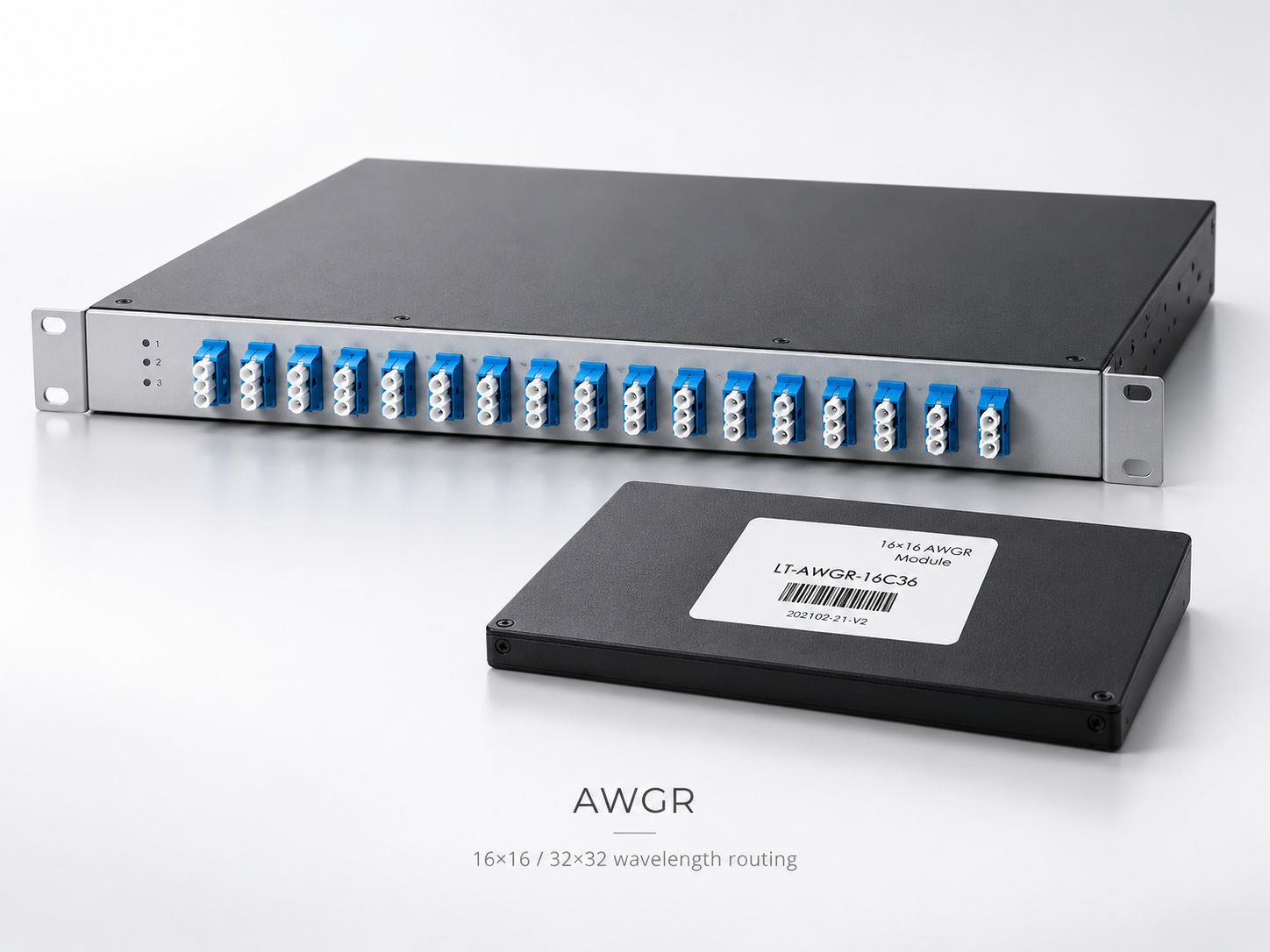
Current AWGR Equipment Products
Both 16×16 and 32×32 variants are available as equipment-level products. The WooCommerce products below link to each item's detailed technical specifications.

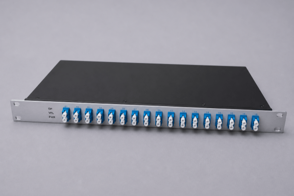
16×16 vs 32×32 Equipment Specifications
Both equipment formats have the same published enclosure dimensions. The port count changes the routing matrix and specified insertion-loss range.
| Parameter | 16×16 AWGR | 32×32 AWGR |
|---|---|---|
| Input / Output Ports | 16 × 16 | 32 × 32 |
| Operating Band | C-band | C-band |
| Channel Spacing | 100 GHz | 100 GHz |
| Insertion Loss | 2–6 dB | 3–7 dB |
| Adjacent Channel Isolation | ≥25 dB | ≥25 dB |
| Non-Adjacent Isolation | ≥30 dB | ≥30 dB |
| Return Loss | ≥25 dB | ≥25 dB |
| Polarization Dependent Loss (PDL) | ≤0.5 dB | ≤0.5 dB |
| Polarization Mode Dispersion (PMD) | ≤0.15 ps | ≤0.15 ps |
| Mechanical Size | 484 × 250 × 45 mm | 484 × 250 × 45 mm |
| Operating Temperature | −5 to +65°C | −5 to +65°C |
Before ordering, confirm the exact channel mapping, connector interface and system optical budget. The enclosure alone does not determine optical network compatibility.
How AWGR Equipment Routes Wavelengths
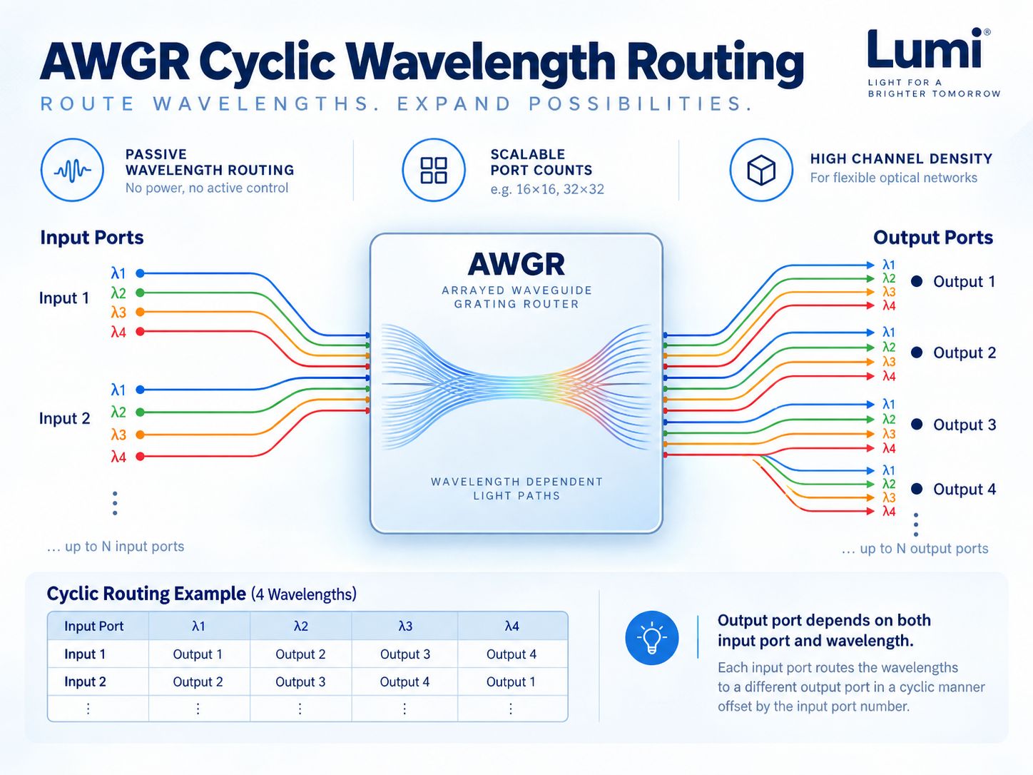
With an AWGR, both the incoming wavelength and its input port determine the corresponding output. A different optical wavelength can change the output route even if the same input port is used.
This optical routing relationship is built into the waveguide structure. Dynamic path selection is possible only when other system elements, such as tunable lasers, select the wavelength.
A complete network still needs transmission, reception, traffic and control functions beyond the AWGR itself.
Equipment vs Module: Deployment Boundary
| Selection point | AWGR Equipment | AWGR Module |
|---|---|---|
| Optical Function | Cyclic wavelength routing | Cyclic wavelength routing |
| Available Port Matrices | 16×16 / 32×32 | 16×16 / 32×32 |
| Channel Spacing | 100 GHz | 100 GHz |
| Enclosure Size | 484 × 250 × 45 mm | 150 × 64 × 16 mm |
| Integration Level | System / equipment | Embedded OEM / subsystem |
| Fiber Handling | Larger multiport installation | Host equipment provides surrounding layout |
| Typical Use | Optical lab, network test and rack-oriented integration | OEM photonic assembly |
Explore AWGR Modules → for designs requiring a smaller internal component.
Why Choose the Equipment Format?
Port Accessibility
An enclosed unit provides more organized access to multiple optical ports during setup and test.
Simplified Mechanical Integration
A pre-enclosed routing component reduces external chassis design compared with a bare module.
System-Level Testing
Suitable where engineers repeatedly connect optical sources, receivers and wavelength-routing paths.
Network Architecture Validation
A defined equipment assembly supports evaluation of wavelength routing within optical testbeds.
Fiber Management, Connectors & Thermal Control
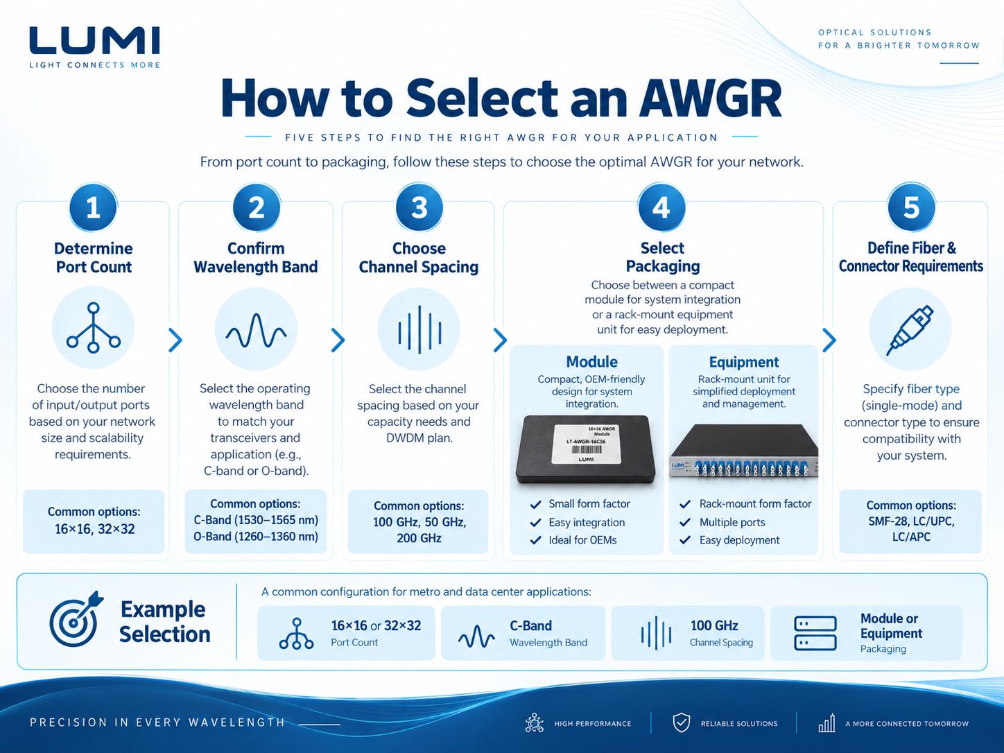
High-port-count equipment requires careful fiber labeling, bend radius and cable organization. A 32×32 routing matrix has 32 input and 32 output connections, so the installation layout matters.
- Ordering options include 0.5 m / 1 m cable or fiber length.
- Connector options include SC, FC and LC families.
- Polish directions include PC, UPC and APC, depending on configuration.
- Current equipment ordering information includes a Ø9 mm cable/fiber direction.
- Equipment specifications list thermal-stabilization provisions; confirm the required TEC integration.
Critical Optical Performance Parameters
Insertion Loss
Account for 2–6 dB (16×16) or 3–7 dB (32×32) AWGR loss along with every other passive link loss.
Channel Isolation
Specified adjacent isolation ≥25 dB and non-adjacent isolation ≥30 dB support crosstalk evaluation.
PDL / PMD
PDL ≤0.5 dB and PMD ≤0.15 ps are important optical link characteristics.
Wavelength & Temperature
Match transmitter wavelength channels to the AWGR passband over expected temperature and control conditions.
Where AWGR Equipment Fits
AWGR equipment can serve as a multi-port optical routing unit inside larger communication and photonic-system architectures.
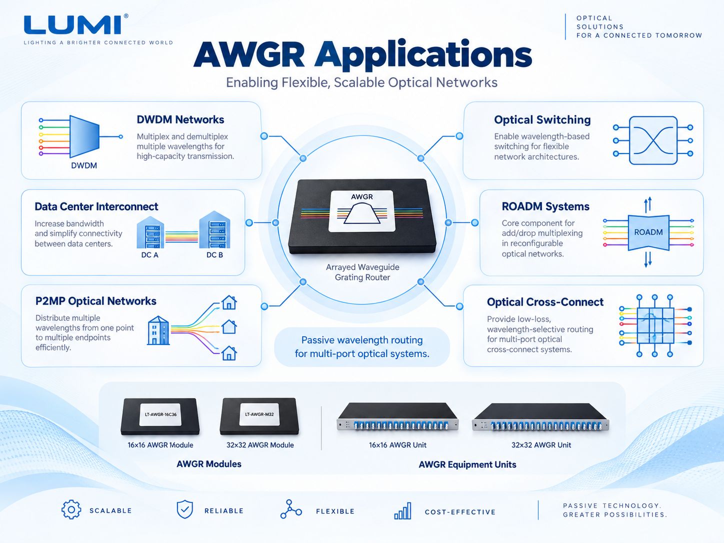
DWDM / Metro Systems
Multi-direction wavelength routing within a larger optical communication platform.
Optical Switching Testbeds
Evaluate wavelength-selected paths controlled by external optical sources.
ROADM Architectures
Support wavelength-management system research and integration.
Backbone Optical Networks
Provide high-port-count routing capability inside broader network equipment designs.
Laboratory Characterization
Connect instruments to repeatable multiport optical paths.
Data Center Photonics
Explore high-density passive wavelength-routing fabric concepts.
AWGR Equipment in Wavelength-Routed Testbeds
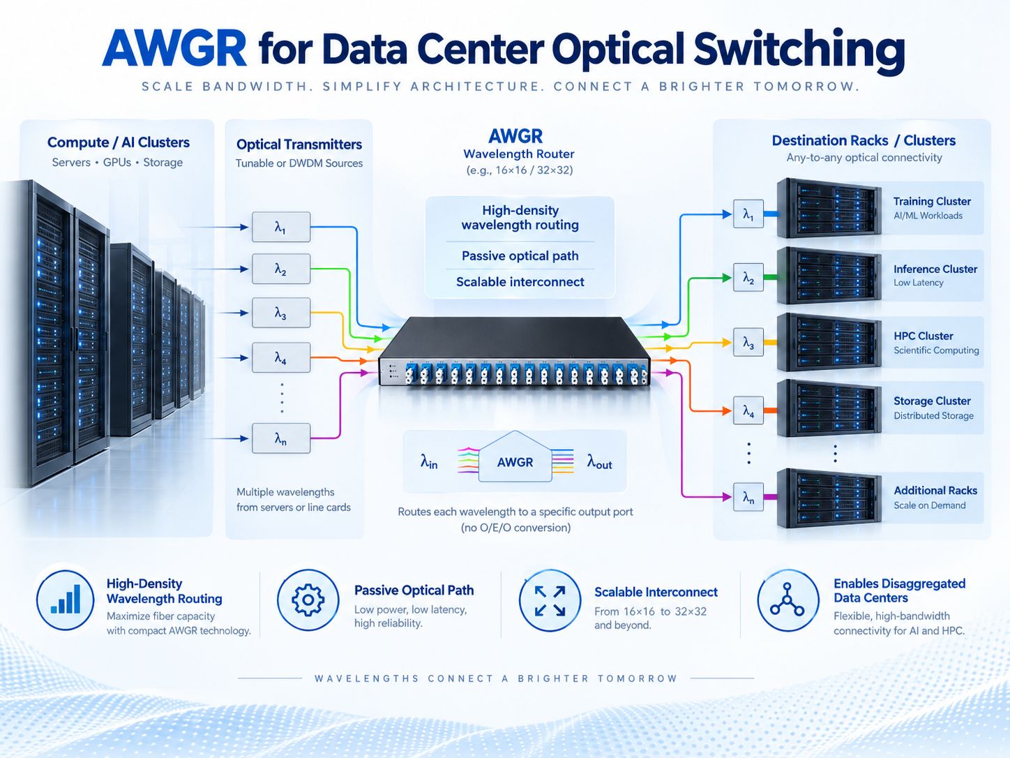
AWGR equipment can be used to evaluate wavelength-routed optical links between multiple endpoints. Transmitters or tunable lasers select channels, the AWGR supplies optical port mapping, and receivers capture the selected paths.
Network functions such as traffic arbitration, buffering and control-plane decisions remain outside the device. The AWGR does not make packet-routing decisions.
For data-center optical interconnect studies, confirm the complete system topology, wavelength-locking method, transceiver performance and power margin.
Preparing an AWGR Equipment RFQ
- Network Matrix16×16 or 32×32 with required port map.
- Optical GridC-band, 100 GHz spacing and starting ITU channel.
- Optical BudgetInsertion loss, channel isolation, transmitter drift and reflection constraints.
- InstallationConnector, fiber length, port labeling, rack layout and thermal design.
AWGR Equipment — FAQ
What is the difference between AWGR equipment and module?
Both perform wavelength-dependent routing, but the equipment uses a larger 484 × 250 × 45 mm enclosure while the module is 150 × 64 × 16 mm.
What does 32×32 equipment mean?
It provides 32 optical input and 32 output ports configured for cyclic wavelength routing.
Does AWGR equipment replace an Ethernet switch?
No. It routes optical wavelength channels. Traffic, packet and network-control functions are provided by external systems.
What channel spacing does Lumi equipment use?
Current equipment offerings are specified for C-band operation and 100 GHz channel spacing.
Can AWGR equipment be used in a laboratory?
Yes. A larger enclosure can facilitate multiport connection and evaluation inside laboratory photonic systems.
How should I select connectors and fiber length?
Match the product ordering options to the port-management plan, connector family, polish and available installation space.
Request an AWGR Equipment Configuration
Provide your optical network topology, matrix size, wavelength grid, loss budget and interface requirements. Lumi can review the relevant AWGR equipment configuration.