
Cooled BOSA Modules for Integrated Optical Transmission and Reception
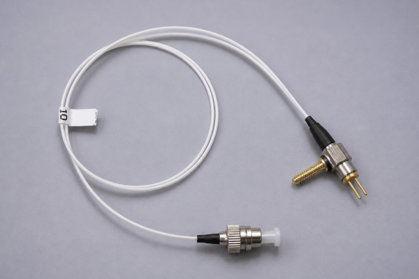
Lumi's cooled BOSA brings a DFB laser transmitter, high-linearity PIN photodiode receiver, wavelength-division multiplexing optics, optical isolation and thermal-control elements into one fiber-pigtail assembly.
Designed for CATV, Radio Frequency over Glass (RFoG), analog optical transport and project-specific single-fiber bidirectional links, the assembly provides an optical building block for OEM systems—not a finished plug-in transceiver.
- DFB laser Tx with integrated TEC and thermistor
- High-linearity PIN photodiode Rx
- Tx/Rx wavelength separation over single-mode fiber
- SC / FC / LC connector configurations, subject to wavelength and interface confirmation
What Is a BOSA Module?
A Bi-Directional Optical Sub-Assembly (BOSA) integrates an optical transmitter and receiver with a shared fiber interface. It uses wavelength management to direct outgoing light into a fiber and incoming light toward a photodetector.
Transmitter (Tx)
The DFB laser creates a selected optical carrier and the package couples that signal into the fiber path.
WDM Optical Path
Wavelength-selective optics route the transmit and receive channels to their respective optical paths over a common fiber.
Receiver (Rx)
The PIN photodiode detects the incoming light. The host equipment provides the necessary receiver-side electronics.
Product scope: TOSA (transmit only) and ROSA (receive only) describe optical functions. Lumi's currently listed integrated product in this family is the cooled BOSA module. Explore the Optical Sub-Assemblies overview for the architecture comparison.
How Transmit and Receive Paths Share One Fiber
The wavelength pair must be planned as a complete system requirement: the remote end must transmit at the wavelength expected by the local receiver and receive the wavelength sent by the local laser.
DFB Laser & Isolator
The DFB source generates the outgoing optical carrier; isolation helps limit feedback toward the laser cavity.
WDM + Single-Mode Fiber
WDM optics combine and separate the relevant wavelengths at the shared external fiber interface.
PIN Photodiode
Incoming optical power is routed to the PIN detector, with amplification and subsequent signal processing handled by the host.
Tx and Rx wavelengths cannot be freely interchanged. The ordered wavelength pair, WDM path, connector, return-loss requirements and far-end system must be mutually compatible.
Cooled BOSA Module with Fiber Pigtail
The current configuration combines an actively temperature-controlled DFB transmitter with a high-linearity PIN receiver and integrated wavelength-management elements. It is suited to optical-system developers seeking a compact shared-fiber Tx/Rx sub-assembly.
- Optical source: single-longitudinal-mode DFB laser transmitter
- Detector: high-linearity PIN photodiode receiver
- Thermal elements: TEC and thermistor; external controller required
- Optics: WDM filter, optical isolator, single-mode fiber pigtail
- Typical use: CATV, RFoG and other analog-oriented bidirectional fiber OEM equipment
Representative Transmitter and Receiver Specifications
Key performance values for the current cooled BOSA family are summarized below. Minimum, typical and maximum ratings should be read distinctly; performance depends on the stated test conditions and ordered configuration.
DFB Laser Transmitter
| Parameter | Published Value |
|---|---|
| Threshold current | 15 mA typ. |
| Optical output at 30 mA | 2 mW typ. (1.8 mW min.) |
| Slope efficiency | 0.14 W/A typ. |
| SMSR | 35 dB typ. (30 dB min.) |
| Linewidth | 3 MHz typ. |
| Optical isolation | ≥25 dB |
| Tx bandwidth (−3 dB) | ≥1.2 GHz |
| Thermistor resistance at 25°C | 10 kΩ typ. |
High-Linearity PIN Receiver
| Parameter | Published Value |
|---|---|
| Responsivity | ≥0.8 A/W |
| Bandwidth | ≥1.5 GHz |
| Capacitance | 0.5 pF typ. (0.6 pF max.) |
| Dark current | ≤5 nA |
| Return loss | ≥40 dB |
| IMD2 at 1550 nm | ≤−70 dBc |
| IMD3 at 1550 nm | ≤−80 dBc |
| Detector | PIN photodiode |
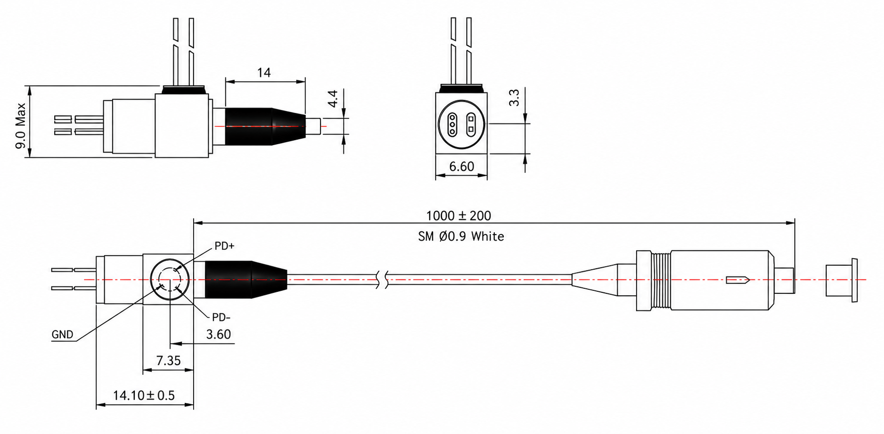
Values above refer to the present published cooled BOSA platform, not every future variant. For mechanical drawings, electrical pins, limits and full test conditions, open the specific product page.
Explore Lumi BOSA Products
Browse actual BOSA products from the Lumi catalogue. Open the product record to review complete transmitter and receiver characteristics, mechanical information and ordering options.

This live catalogue currently centers on the cooled BOSA with fiber pigtail. Related technologies such as TOSA and ROSA are not displayed as independently available products.
BOSA Wavelength and Fiber-Interface Options
A valid order must define both optical directions. Different wavelengths and fiber interfaces are available within the product family, but not every theoretical combination is an approved configuration.
| Selection Item | Current Product Options | Engineering Consideration |
|---|---|---|
| Transmit wavelength | 1270, 1290, 1310, 1450, 1470, 1490, 1550, 1610 nm | Choose according to the outgoing channel and remote receiver |
| Receive wavelength | 1310 or 1550 nm | Must match incoming channel and WDM optics |
| Fiber | Single-mode | Check wavelength, budget and pigtail details |
| Connector family | SC / FC / LC, configuration dependent | Confirm mating interface and mechanical clearance |
| Connector polish | PC / UPC / APC options, configuration dependent | Consider optical reflections and installed system requirements |
| Operating case temperature | −40 to +85°C with heatsink | Requires suitable heat removal and external TEC control |
The wavelength list is a configurable family offering, not a claim that all combinations are held in stock. Share the complete Tx/Rx pair and connector specification with Lumi before ordering.
Why Linearity Matters for CATV and RFoG
For RF-over-fiber systems, optical output power is only one part of link performance. Distortion and receiver linearity can influence the integrity of transported analog RF signals.
CSO
Composite Second Order: transmitter specification includes a −55 dBc maximum value under its defined condition.
CTB
Composite Triple Beat: transmitter specification includes a −60 dBc maximum value under its defined condition.
IMD2
Receiver second-order intermodulation distortion at 1550 nm: ≤−70 dBc.
IMD3
Receiver third-order intermodulation distortion at 1550 nm: ≤−80 dBc.
The published analog specifications make the current cooled BOSA especially relevant to CATV/RFoG-oriented development. Digital-link compatibility should be confirmed from its actual modulation, bandwidth and system requirements rather than assumed from a generic “high speed” description.
TEC, Thermistor and Optical Isolation
Thermoelectric Cooler
The integrated TEC permits the external controller to regulate the DFB laser temperature. Design sufficient current, voltage and heat-sinking capacity.
Thermistor Feedback
A nominal 10 kΩ thermistor at 25°C supports the external temperature feedback loop. Confirm the electrical pinout before board design.
Optical Isolation
Optical isolation of at least 25 dB helps limit unwanted light returning to the transmitter and affecting its performance.
The presence of TEC and thermistor does not make the BOSA self-regulating. The host equipment must provide an appropriate temperature controller and mechanical heat path.
Application Areas for Cooled BOSA Modules
CATV Optical Nodes
Analog-oriented transmission and reception for optical cable-television system components, subject to RF specifications and link budgeting.
Radio Frequency over Glass
RFoG access equipment using bidirectional fiber interfaces and the required two-way wavelength architecture.
Analog Optical Links
OEM optical link designs in which Tx/Rx distortion, bandwidth and optical stability are important.
Single-Fiber Tx/Rx Links
Systems requiring transmit and receive paths on one single-mode fiber through wavelength separation.
Optical Instrumentation
Specialized equipment built around supported wavelength, optical power and receiver requirements.
Custom Fiber Modules
OEM integration into a customer's electronic and mechanical platform, including thermal and connector design.
BOSA vs TOSA, ROSA and Complete Optical Transceivers
| Component | Main Function | What the Host Still Needs |
|---|---|---|
| TOSA | Transmitter-side sub-assembly | Receiver path and host electronics |
| ROSA | Receiver-side sub-assembly | Transmitter path and host electronics |
| BOSA | Bidirectional transmitter + receiver with shared optical path | Laser driver, receiver circuitry, TEC control, system PCB and housing |
| Finished Transceiver | System-level electrical and optical interface | Depends on module and standards requirements |
Because a BOSA is the internal optical sub-assembly, it is not automatically a complete SFP, ONU or CATV node. Request a finished-equipment solution separately when the host electronics, power, control and mechanical enclosure are part of the sourcing requirement.
How to Specify a BOSA Module
Define Tx and Rx Wavelengths
Specify both directions and describe the optical system at the remote end.
Set Optical Power and Loss
Determine transmitted fiber power, return loss and receiver input conditions.
Define Analog or Digital Needs
State modulation, RF distortion, receiver bandwidth and acceptable noise.
Plan TEC Control
Include operating environment, case heat path and thermistor interface.
Choose Fiber and Connector
Provide single-mode fiber length, connector type and polish.
Define Qualification and Volume
Share intended sample quantity, forecast and test documentation requirements.
BOSA Package and Product Documentation
Reference views from the current BOSA product documentation. Mechanical dimensions and final pin mapping should always be checked against the selected variant.
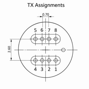
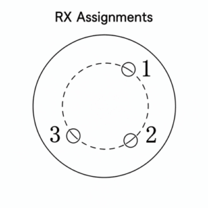
Open product details for pin configuration, limits and ordering information →
Frequently Asked Questions About BOSA Modules
What does BOSA stand for?
Bi-Directional Optical Sub-Assembly, integrating an optical transmitter and receiver into a shared fiber optical path.
Does BOSA mean a complete optical transceiver?
No. A BOSA is the optical sub-assembly; the final transceiver or host equipment needs driver electronics, receiver circuit, controls, power and mechanical interfaces.
Why are two optical wavelengths required?
Separate transmit and receive wavelengths permit wavelength-selective routing through one fiber, with the WDM element directing the correct wavelength to the correct optical path.
Can I choose any Tx and Rx wavelength combination?
No. The listed wavelengths are configurable options, not evidence that every combination is valid. The WDM architecture and remote endpoint must be checked together.
What DFB laser is inside the cooled BOSA?
The current platform uses a DFB transmitter with typical optical output of 2 mW at 30 mA, typical 35 dB SMSR and typical 3 MHz linewidth under specified conditions.
Why is receiver linearity important?
Analog CATV and RFoG signals are sensitive to distortion. The current cooled BOSA includes receiver IMD2/IMD3 and transmitter CSO/CTB characteristics relevant to RF-over-fiber design.
Does the integrated TEC work without external electronics?
No. The module contains TEC and thermistor elements; the host system must control TEC current and manage heat sinking.
Which connectors are available?
SC, FC and LC connector families, with PC, UPC or APC polish options depending on the ordered configuration.
What is RFoG?
Radio Frequency over Glass, an architecture carrying cable RF services over optical fiber.
What should I include in a quotation request?
Include the application, Tx/Rx wavelength pair, fiber optical power budget, receiver bandwidth/linearity, signal format, connector details, operating conditions and anticipated quantity.
Discuss a Cooled BOSA Configuration with Lumi
Share your Tx and Rx wavelengths, CATV/RFoG or other optical-link requirements, launch power, receiver specifications, fiber interface, thermal constraints and estimated production quantity.