
Compact 16×16 & 32×32 AWGR Modules
Lumi C-band 100 GHz AWGR modules bring cyclic wavelength routing into a compact 150 × 64 × 16 mm package. Select 16×16 or 32×32 routing for DWDM subsystems, optical interconnects and OEM photonic equipment.
A module is the appropriate product form when your engineering team manages the surrounding enclosure, fiber routing and optical system interfaces.
What Is an AWGR Module?
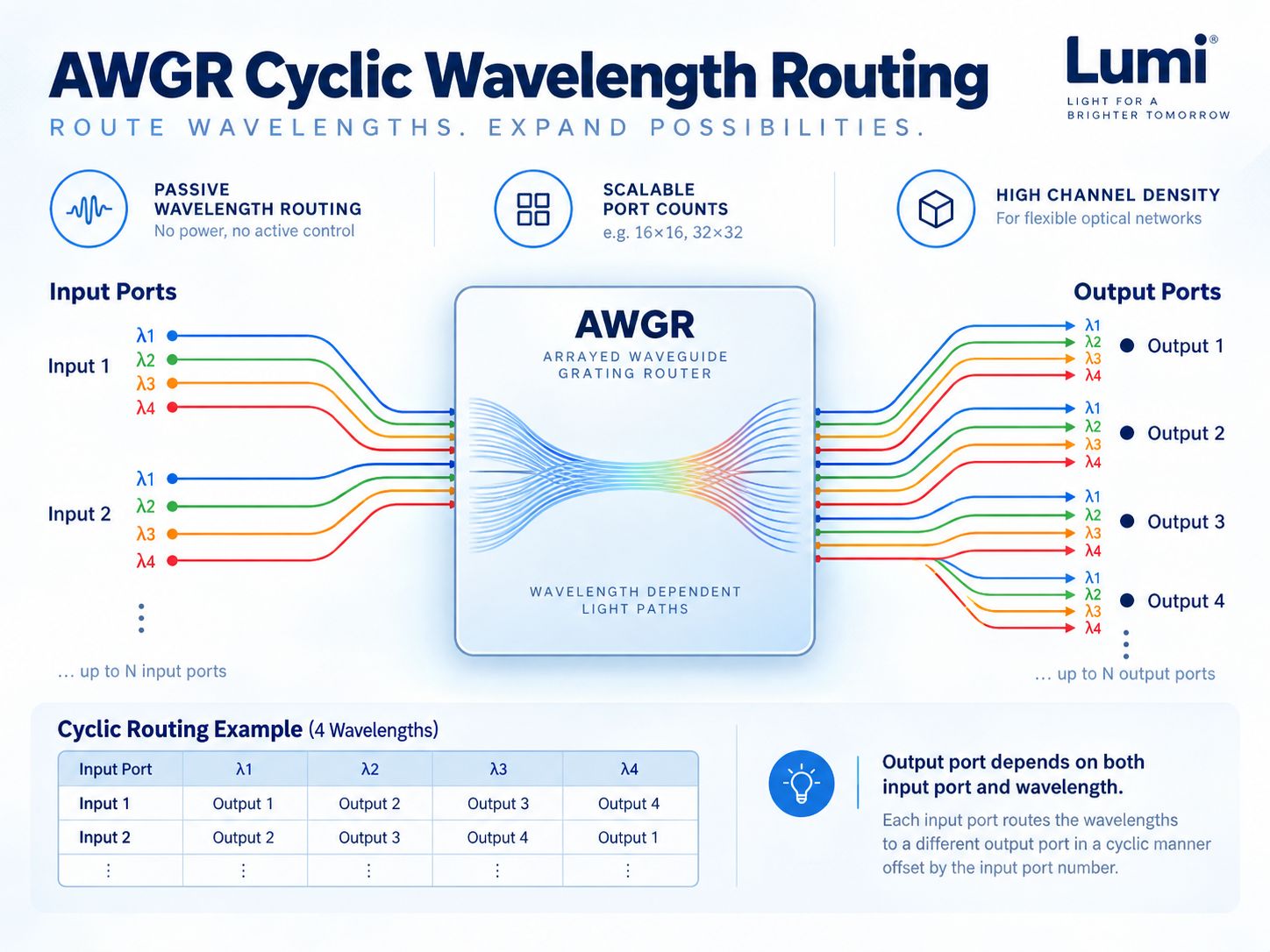
An AWGR module is an enclosed wavelength-routing component designed for installation inside a larger optical product. Multiple input fibers carry wavelength channels into the device; waveguide routing sends each wavelength/input-port combination to its prescribed output.
The AWGR route is created optically, not by Ethernet packet inspection. Current module ordering data also includes thermal-stabilization provisions; the routing core remains passive even when the module uses temperature control.
- Small package suited to OEM engineering
- Input- and wavelength-dependent cyclic output mapping
- 16×16 and 32×32 variants with 100 GHz spacing
- Integrates with customer fiber management and network design
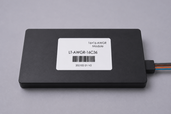
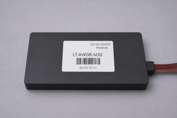
Current AWGR Module Products
Browse the two current module configurations. Product images and specification details are linked directly to WooCommerce, so newly assigned products can be maintained without rebuilding this page.

16×16 vs 32×32 Module Specifications
The two modules share the same mechanical envelope but differ in port count and insertion-loss allowance. Compare the actual wavelength plan and link margin before choosing matrix size.
| Parameter | 16×16 AWGR | 32×32 AWGR |
|---|---|---|
| Input / Output Ports | 16 × 16 | 32 × 32 |
| Operating Band | C-band | C-band |
| Channel Spacing | 100 GHz | 100 GHz |
| Insertion Loss | 2–6 dB | 3–7 dB |
| Adjacent Channel Isolation | ≥25 dB | ≥25 dB |
| Non-Adjacent Isolation | ≥30 dB | ≥30 dB |
| Return Loss | ≥25 dB | ≥25 dB |
| Polarization Dependent Loss (PDL) | ≤0.5 dB | ≤0.5 dB |
| Polarization Mode Dispersion (PMD) | ≤0.15 ps | ≤0.15 ps |
| Mechanical Size | 150 × 64 × 16 mm | 150 × 64 × 16 mm |
| Operating Temperature | −5 to +65°C | −5 to +65°C |
Specifications shown here reflect the current Lumi module product family. Connector and starting-channel selections depend on the final ordered configuration.
Choose the Right AWGR Module
16×16 Module
Choose where 16 input/output directions meet the routing architecture and a 2–6 dB specified insertion-loss range fits the optical budget.
32×32 Module
Choose for larger wavelength-routing matrices where additional port density justifies the 3–7 dB specified insertion-loss range.
Mechanical Integration
Both variants share 150 × 64 × 16 mm module dimensions. Allow space for optical fibers, bending radius and thermal requirements.
Higher port count is not universally better: optical loss, channel plan and the number of physical fiber connections must be reviewed together.
Fiber, Connector & Channel Configuration
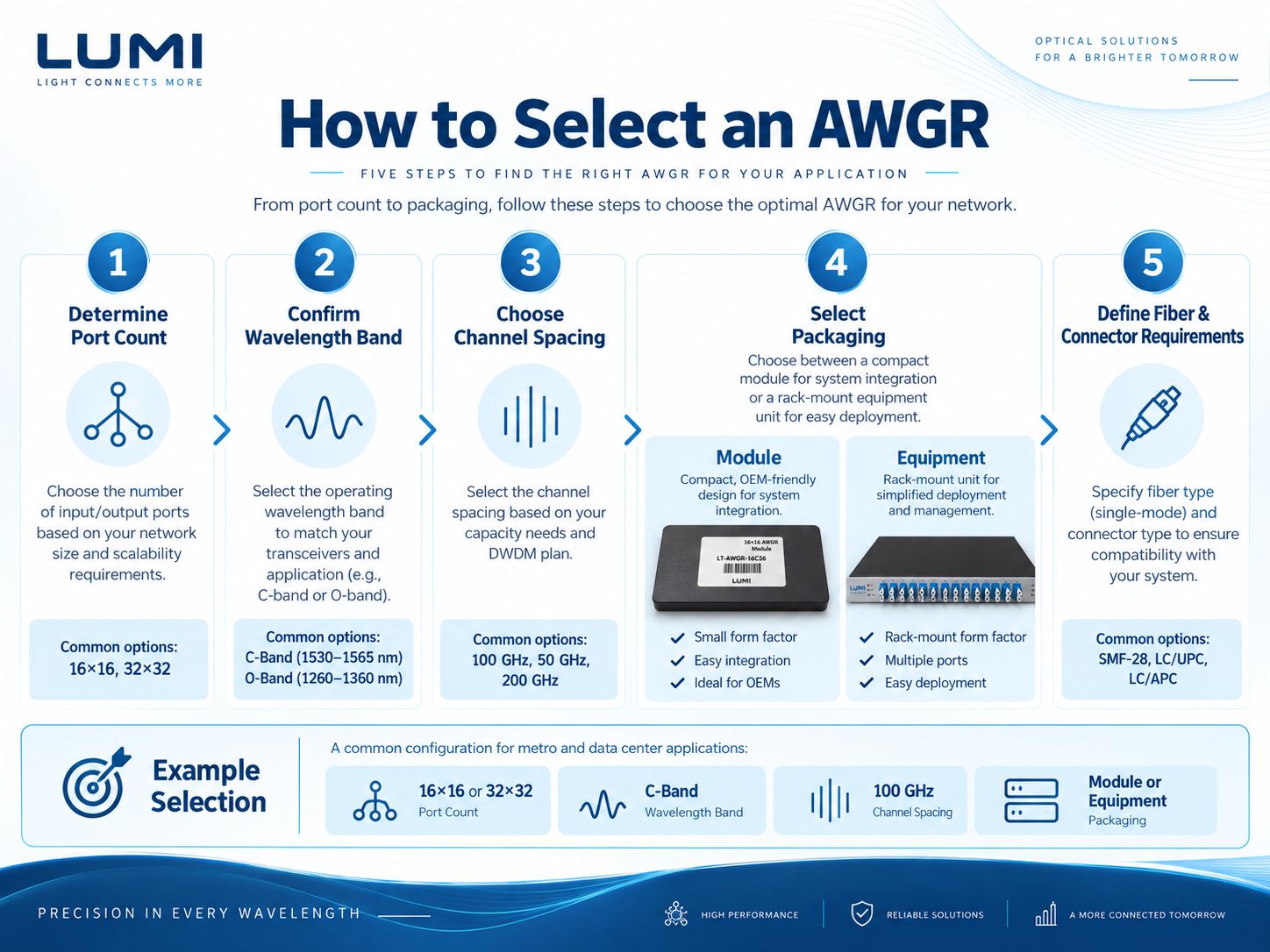
When ordering a module, specify the complete fiber interface. Existing ordering directions include 0.5 m and 1 m fiber lengths, SC/FC/LC connector families and PC/UPC/APC polish types, according to the selected product configuration.
- 100 GHz C-band channel plan and starting ITU channel
- Port numbering and routing matrix
- Fiber length and allowable bend radius
- Connector family and end-face polish
- Thermal stabilization and host power provision
Polish and connector format should match the surrounding optical network, especially when reflections and return loss are important.
Optical Performance in the Host System
Insertion Loss
Include module insertion loss in the complete optical power budget together with splice, connector and fiber losses.
Adjacent Channel Isolation
Specified adjacent isolation of at least 25 dB helps characterize wavelength crosstalk.
Return Loss & Connectors
Specified AWGR return loss is at least 25 dB; surrounding connector and network reflections still matter.
PDL, PMD & Stability
PDL ≤0.5 dB and PMD ≤0.15 ps; review temperature stabilization and the transmitter wavelength grid.
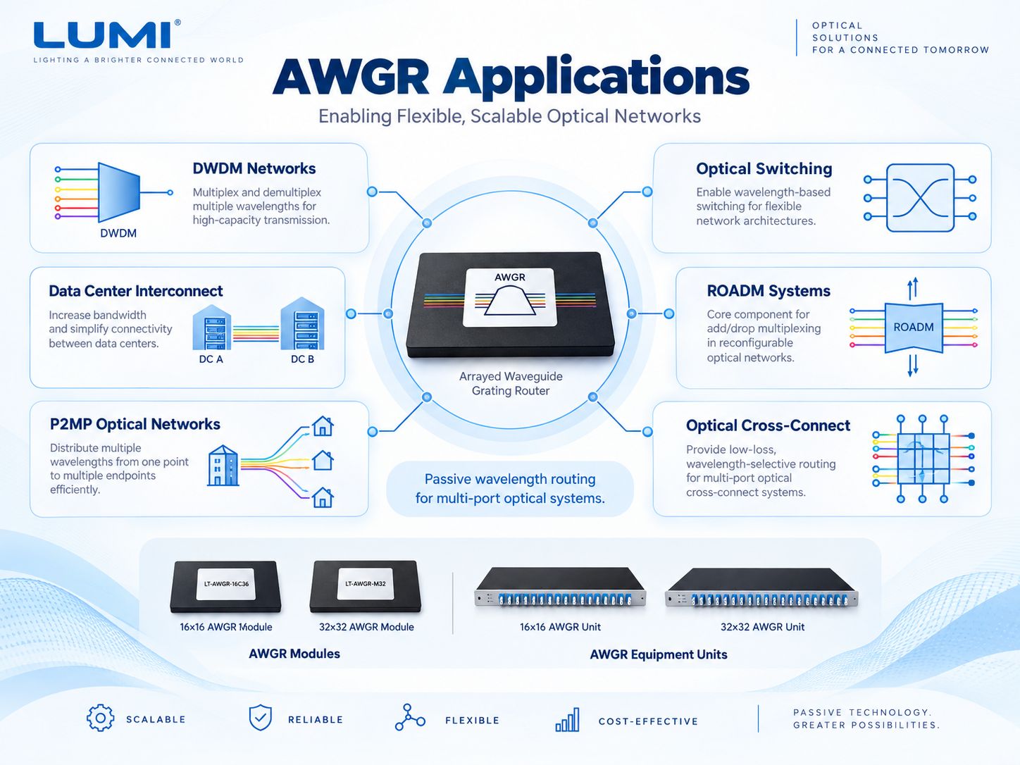
Where AWGR Modules Are Used
Module-level packaging is most useful when the AWGR is integrated inside a customer's photonic device rather than used as a separate equipment chassis.
DWDM Subsystems
Integrate passive wavelength routing into optical-channel management equipment.
ROADM Architectures
Apply as a wavelength-routing component inside broader reconfigurable network subsystems.
Optical Test Platforms
Create repeatable multi-port optical paths for characterization and photonic test setups.
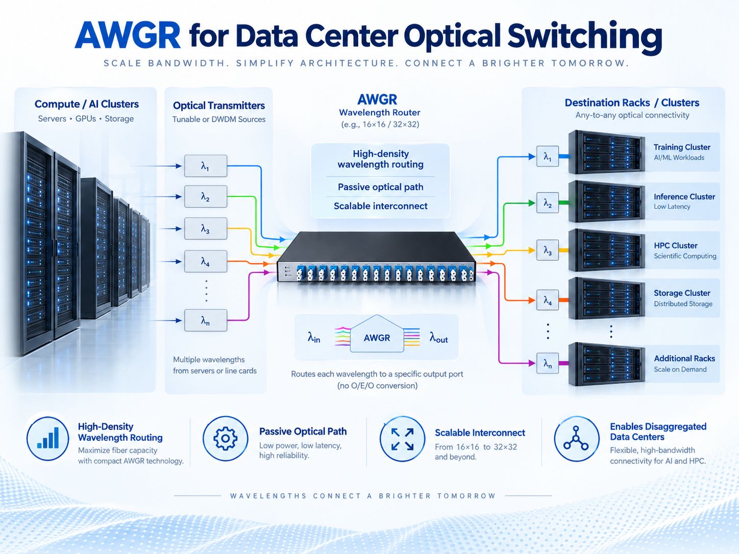
Data Center Research
Explore high-density wavelength-selectable optical interconnect fabrics.
Optical Switching R&D
Use externally selected wavelengths to determine routes through the passive AWGR.
OEM Optical Systems
Build a wavelength-routing component into customer-designed network and photonic products.
AWGR Modules for Optical Interconnect Research
A compact AWGR module can form the routing core of an experimental or OEM wavelength-routed network. By selecting an optical wavelength at the transmitter, the surrounding system determines which AWGR output is reached.
That functionality does not perform packet switching, buffering, link management or network scheduling. External sources, optical receivers and network-control electronics provide those functions.
Review the complete system architecture before determining whether the module meets an intended data-center or high-performance-computing application.
AWGR Module vs Equipment
| Selection point | AWGR Module | AWGR Equipment |
|---|---|---|
| Routing Principle | Cyclic wavelength routing | Cyclic wavelength routing |
| Current Port Matrices | 16×16 / 32×32 | 16×16 / 32×32 |
| Channel Spacing | 100 GHz | 100 GHz |
| Mechanical Envelope | 150 × 64 × 16 mm | 484 × 250 × 45 mm |
| Integration | Embedded OEM design | Enclosed system / laboratory |
| Fiber Management | Customer host handles more | Larger enclosure supports multiport organization |
Explore AWGR Equipment → or return to the AWGR family overview →
Specify Your AWGR Module Requirement
- Matrix & Ports16×16 or 32×32 and the required port mapping.
- Channel PlanC-band grid, 100 GHz spacing and starting channel.
- Loss BudgetMaximum allowable optical loss and isolation requirements.
- Fiber InterfaceLength, connector polish and mechanical installation layout.
AWGR Module — Technical FAQ
What is an AWGR module?
A compact arrayed-waveguide device for cyclic routing of optical wavelength channels between multiple input and output ports.
What is the size of Lumi AWGR modules?
Both current 16×16 and 32×32 C-band 100 GHz module versions have a published package size of 150 × 64 × 16 mm.
Can a module replace an Ethernet switch?
No. AWGR wavelength routing is a passive optical function, not packet switching or network orchestration.
Why choose 32×32 instead of 16×16?
Use 32×32 for a larger port matrix while checking its higher specified insertion-loss range and overall optical link budget.
Do the modules require electrical power?
The optical routing core is passive, but current module specifications include a TEC, so confirm thermal and power integration.
Which connectors are supported?
Current ordering descriptions include SC, FC and LC families and several polish variants depending on the selected configuration.
Discuss Your AWGR Module Design
Share the port matrix, wavelength schedule, optical budget and fiber-interface requirements for your next photonic system. Lumi can evaluate the available module configurations.